Can Measurement and Control Systems Handle Corrosive Flue Gas?


Yes. Measurement and control systems can handle corrosive flue gas when the sensing method, wetted materials, sampling arrangement, installation point, and maintenance strategy are selected as one engineered system. A transmitter or analyzer that performs well in clean, dry gas can fail quickly when exposed to acid dew point condensation, chlorides, sulfur compounds, alkaline dust, unburned hydrocarbons, or abrasive fly ash. The issue is rarely sensor accuracy alone. Long-term performance depends on whether the measurement path remains chemically stable, physically open, thermally controlled, and representative of the actual gas stream.
Corrosive flue gas is common in combustion processes involving coal, biomass, municipal waste, hazardous waste, refinery fuel gas, sulfur-bearing feedstocks, and chemical reaction exhaust. Its composition changes with fuel quality, excess air, burner condition, load changes, sorbent injection, and upstream gas-cleaning equipment. A system must therefore be designed for the harshest credible operating condition rather than for an average composition recorded during stable operation.
Why flue gas becomes difficult to measure
Dry gas at a high temperature is often less destructive than gas that cools locally. Sulfur dioxide, hydrogen chloride, hydrogen fluoride, nitrogen oxides, and other constituents may remain manageable while they are fully gaseous. When the gas temperature falls below the relevant acid dew point, moisture condenses and dissolves those compounds into an acidic liquid film. That film can attack probe bodies, impulse lines, sample tubing, valves, filters, analyzer components, cable glands, and mounting hardware.
Condensation also changes the measurement itself. Water-soluble compounds can be partially removed from the sampled gas, so an analyzer may report a lower concentration than exists in the stack. Deposited solids can absorb reactive gases, restrict flow, or create delayed readings. A pressure tap that is clear at startup may plug after repeated thermal cycling. These faults can resemble sensor drift even when the sensing element remains functional.
Particulate loading introduces a separate failure mechanism. Ash, catalyst fines, soot, lime, and salt deposits can erode exposed surfaces or form insulating layers on temperature sensors and optical windows. A slow temperature response caused by a coated thermowell is not equivalent to a failed temperature element; replacing the element alone leaves the underlying problem unresolved. Likewise, a rising differential pressure across a sample filter may indicate dust loading, moisture-induced agglomeration, or a chemical reaction between deposits and condensate. The corrective action differs for each cause.
Direct measurement and extractive sampling are different choices
The first design decision is whether the instrument measures directly in the flue duct or stack, or whether a conditioned sample is transported to an analyzer cabinet. Neither arrangement is automatically superior.
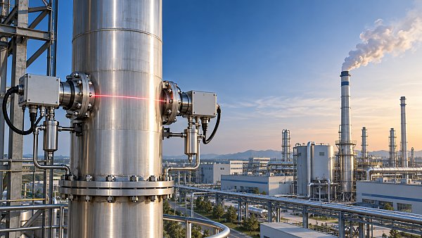
In-situ measurement keeps the gas in its original process environment. Optical analyzers, cross-duct devices, zirconia oxygen probes, tunable laser systems, protected thermocouples, and certain flow technologies can avoid many sample-line losses. Their limitations are exposure to dust, vibration, optical fouling, temperature gradients, alignment changes, and non-uniform gas profiles. A line-of-sight instrument may provide a path-average reading, while an extractive probe captures gas from one physical location. Those values can differ legitimately in a poorly mixed duct.
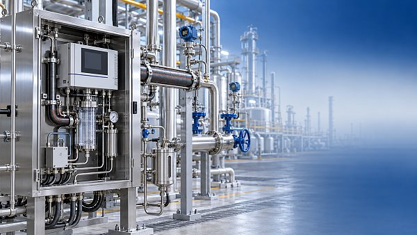
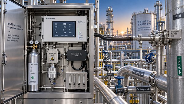
Extractive measurement offers controlled pressure, temperature, filtration, flow, and calibration conditions at the analyzer. It is often appropriate where several components must be measured using one sample train or where the sensing technology cannot be installed in the stack. Yet it creates a second process: the sample transport system. The gas composition must survive probe extraction, filtration, heated transfer, conditioning, and delivery. Every cold spot, dead leg, reactive surface, or leaking fitting can change the sample before it reaches the analyzer.
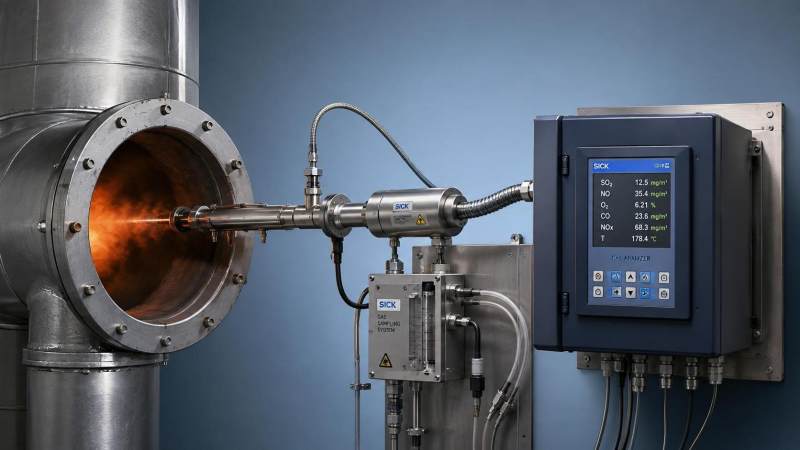
A hot-wet extractive arrangement maintains the sample above its condensation temperature and measures water-containing gas directly. This approach preserves soluble components more effectively, but demands heated probes, heated filters, heated lines, compatible seals, and disciplined temperature control. A dry-basis arrangement removes water before analysis. It can suit some analytical methods, but the removal process and any conversion between wet and dry reporting bases must be understood. Comparing a wet-basis in-situ reading with a dry-basis extractive reading without correcting the basis is a common source of apparent disagreement.
Material compatibility begins at the process boundary
Material selection cannot be reduced to choosing “corrosion-resistant steel.” Resistance depends on chemical species, concentration, moisture, temperature, oxygen availability, deposit chemistry, and crevice conditions. A material that withstands dry hot gas may be vulnerable beneath a wet chloride-bearing deposit. A polymer liner that resists acid can be unsuitable near a hot probe tip. Elastomer seals often become the weak point before the metal body does.
High-alloy metallic materials, fluoropolymer-lined parts, ceramic elements, glass components, and specialized coatings each have useful roles, but only within their operating limits. The specification should identify every surface that contacts the gas, condensate, deposits, calibration gas, purge gas, and cleaning medium. It should also distinguish permanent exposure from short upset exposure. A wash sequence or shutdown condition can create more severe condensate than normal running conditions.
Weld quality and fabrication details matter. Rough internal tubing, poorly drained low points, threaded crevices, unheated instrument tees, and mixed-metal connections can become initiation sites for deposits and corrosion. A nominally suitable alloy does not compensate for a sample path that traps acidic liquid.
Protect the sample without making it unrepresentative
Probe design should match the physical condition of the gas. A probe exposed to high dust loading needs a position and geometry that reduce direct particle impact while still drawing a representative sample. Excessive shielding can create a stagnant pocket where the temperature drops or the composition differs from the main stream. A short probe may avoid erosion but miss the representative gas zone if stratification is present.
Heated sample systems require more than a stated heat-trace temperature. The complete route must be reviewed: probe filter housing, line terminations, valves, bulkhead fittings, sample pump interface, drain sections, and analyzer inlet. A single unheated compression fitting mounted against a cold wall can become the lowest-temperature point in the system. When acidic condensate forms there, it may cause corrosion, blockage, or a false low reading for soluble gases.
Filtration should be selected for particle size, loading, chemical compatibility, and service access. Very fine filtration can protect downstream components but impose excessive pressure drop and slow response. Coarser filtration may allow abrasive particles into pumps or measurement cells. The useful question is not simply whether a filter captures dust; it is whether its loading behavior remains predictable between maintenance intervals and whether changing it exposes personnel or equipment to deposited acidic material.
Purge systems deserve the same scrutiny. Air or inert purge gas can protect optical windows, probe tips, and pressure ports, but inadequate purge pressure permits dirty gas to backflow into the instrument. Excessive purge flow can dilute a local sample or disturb a low-pressure process. Moisture or oil carried in purge air can deposit contaminants on hot surfaces, especially where the flue gas contains reactive salts.
Measurement quality must be tied to the control action
Corrosive flue-gas instruments often support more than reporting. Oxygen measurements may influence combustion air control. Carbon monoxide can indicate incomplete combustion. Temperature and draft readings influence furnace stability. Acid-gas analyzers can be associated with reagent injection or scrubber operation. When a value drives control, the system needs a defined response to questionable data.
Using a failed analyzer value as if it were valid can create unstable control. Replacing it immediately with a fixed substitute value can also be unsafe if the process is changing. A better architecture distinguishes several states: healthy measurement, degraded confidence, maintenance bypass, confirmed fault, and out-of-range process condition. Signal-quality information should travel with the measurement to the control system rather than remain hidden in a local analyzer diagnostic screen.
Redundancy is valuable only when the redundant channels do not share the same weakness. Two analyzers fed by the same fouled sample probe, heater circuit, filter, or calibration manifold can fail together. Independent sensing paths are more meaningful for high-consequence functions, though they must still be reconciled when readings diverge. A disagreement may arise from a real gas gradient, different reporting bases, delayed sample transport, sensor contamination, or calibration error. Treating every disagreement as a sensor fault can mask a process problem.
Installation location can determine whether the data is usable
A technically capable analyzer installed at the wrong point cannot provide representative process information. Duct geometry, bends, dampers, fans, reagent injection lances, leak-air entry, temperature layering, and gas-cleaning equipment can all create gradients. Oxygen concentration downstream of air leakage may not represent furnace exit oxygen. An acid-gas reading after a scrubber cannot describe the untreated gas entering it. A pressure transmitter connected through long, unheated impulse lines may reflect condensate head rather than duct pressure.
Before finalizing an installation, the process path should be mapped from fuel or feed introduction through combustion, gas cooling, particulate control, reagent injection, and discharge. This identifies where the gas is hottest, where moisture is likely to condense, where contaminants are removed, and where gas composition can become stratified. It also exposes practical constraints: access for probe removal, lifting clearance, safe drainage, electrical isolation, calibration-gas routing, and protected paths for heated lines.
Response time needs similar attention. A control loop cannot react sensibly to a measurement that arrives after a long transport delay. The delay includes probe residence time, line volume, filter loading, pump capacity, conditioning equipment, and analyzer response. A clean system may meet the intended response expectation, while the same system becomes sluggish as deposits accumulate. Trending sample flow, filter differential pressure, line temperature, analyzer signal strength, and calibration deviations can reveal that degradation before the reported concentration becomes obviously wrong.
Common selection errors
- Specifying only the expected gas concentration. Acid formation, water content, temperature excursions, dust chemistry, and cleaning cycles often govern survivability more strongly than the normal concentration range.
- Assuming a high-temperature rating covers corrosive service. Heat resistance and resistance to wet acidic condensate are separate material questions.
- Choosing a dry sample system for a water-soluble target component without examining sample losses. The analyzer can be functioning correctly while the delivered sample no longer represents the stack gas.
- Locating instruments where access is easy but gas is poorly mixed. Convenient maintenance access does not correct an unrepresentative measurement point.
- Using calibration results as the sole health indicator. A zero and span check can pass while a restricted probe, delayed line, or contaminated optical path degrades real process response.
Maintenance is part of the measurement design
Corrosive service calls for planned inspection points rather than reactive replacement after failure. Probe condition, filter deposits, heat-trace performance, drain integrity, sample flow, purge pressure, optical signal level, and enclosure corrosion should be evaluated against operating history. Deposits should be examined when practical, because their appearance can distinguish dry ash accumulation from wet salt formation or acid attack. Repeated plugging at one location often points to an uncontrolled temperature transition or poor drainage, not simply an undersized filter.
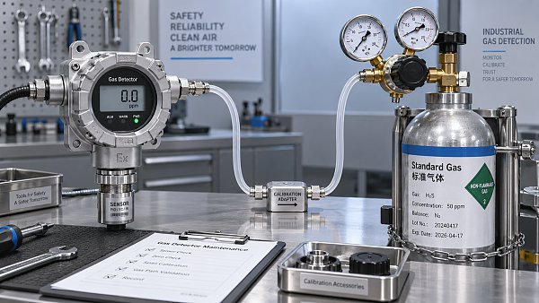
Calibration gas connections need clean, protected routing and a procedure that verifies the full analytical path where appropriate. Injecting calibration gas directly at the analyzer checks analyzer response, but it does not prove that the probe, sample line, filter, and conditioning train are intact. Introducing gas near the probe tests more of the system, though the method must avoid creating unsafe releases or contaminating the process connection.
Measurement and control systems can therefore operate reliably in corrosive flue gas, provided the application is treated as a combined chemical, thermal, mechanical, and signal-integrity problem. The durable design is the one that preserves a representative gas sample or sensing path throughout normal operation, load changes, shutdowns, cleaning cycles, and the maintenance interval between inspections.
Recommended for You
 How to verify accuracy claims for industrial quality analyzersVerify accuracy claims for industrial quality analyzers with calibration checks, independent testing, and clear acceptance criteria. Learn how to reduce risk and buy with confidence.
 How to calculate cooling loads for an industrial analyzer shelterSize industrial analyzer shelter cooling with confidence. Learn to calculate equipment heat, solar gains, and ventilation loads, then select HVAC capacity for reliable analyzer performance.
 Industrial Safety vs. Emission Monitoring: What Are the Differences?What are the main differences between industrial safety and emission monitoring? Compare goals, sensors, response times, and compliance needs to choose the right systems for your facility.
 Is Remote Monitoring Worth the Cost for Small Emission Sources?Is it worth investing in remote monitoring for small emission sources? Compare costs, compliance needs, and potential savings to choose the right solution for your operation.
 How Do You Handle Analyzer Failure During an Environmental Audit?Learn how to handle analyzer failure during environmental compliance audit procedures. Protect evidence, verify data, and restore monitoring with this practical response guide.
 Do VOC Monitors Require Explosion-Proof Certification?Does VOC monitoring require explosion-proof certification? Learn when approval is needed, compare ATEX and IECEx, and choose the right monitor for your site.
 How sample conditioning affects accuracy in petrochemical analyzersImprove accuracy in petrochemical analyzers with smarter sample conditioning. Discover how phase control, filtration, and transport design prevent bias and deliver reliable process data.
 How to troubleshoot sensor drift in industrial gas detectorsIndustrial gas detectors showing sensor drift? Learn how to verify calibration gas, identify root causes, and determine when sensor replacement is needed for reliable monitoring.
 How to judge whether a competitive price reflects real valueCompetitive Price: learn how to compare scope, compliance, performance, and lifecycle costs to identify real value, reduce risk, and make smarter purchasing decisions.
 When custom gas analysis is the right fit for complex process streamsCustom gas analysis for complex process streams: learn when tailored sampling, interference control, and reliable measurement design deliver confident decisions.
 When does a laser gas analyzer meet stack emissions monitoring needs?Laser gas analyzer for stack emissions: learn when it delivers fast, reliable data, how to assess installation risks, and what to verify for CEMS compliance.
 How to select a hazardous gas analyzer for confined spacesHazardous gas analyzer selection for confined spaces: compare sensors, sampling, certifications, alarms, and maintenance to protect workers and choose with confidence.
 When is a single gas analyzer sufficient for workplace safety monitoring?Discover when a single gas analyzer delivers reliable workplace safety monitoring, and learn the key limits, calibration needs, and risks that require broader detection.
 How to choose an ambient gas analyzer for low-level leak detectionAmbient gas analyzer selection for low-level leak detection: compare sensitivity, cross-sensitivity, sampling design, alarms, and calibration for reliable site performance.
 How to tell when an oxygen sensor needs replacementOxygen sensor replacement signs explained: learn how live data, fault codes, wiring checks, and exhaust inspections pinpoint the real issue before you buy.
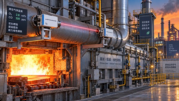
 How laser gas analyzers improve combustion control in steel furnacesLaser gas analyzer for steel industry applications delivers fast in-situ O₂ and CO data to optimize furnace combustion, cut fuel waste, and improve steel heating stability.
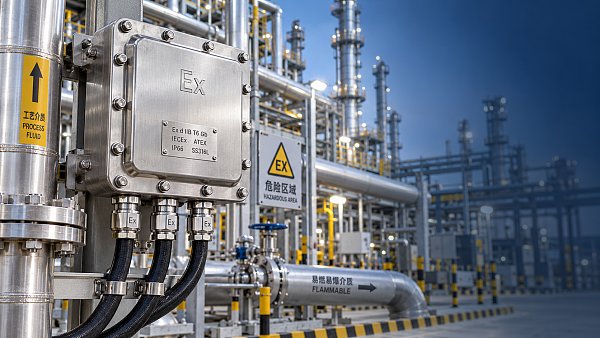
 How to verify whether explosion proof equipment meets site requirementsExplosion proof equipment verification made practical: match zones, gas or dust groups, temperature classes, certificates, and installation conditions for confident compliance.
 How industrial gas analysis helps detect contamination before releaseIndustrial Gas Analysis helps detect moisture, oil, oxygen, and toxic contaminants before release—protecting processes, ensuring compliance, and reducing costly risks.
 When is electrochemistry detection the right choice for water analysis?Electrochemistry detection for water analysis: learn when fast, reliable monitoring of ions, chlorine, pH, and more delivers actionable results.
 How industrial standards reduce quality risks in supplier selectionIndustrial Standard guidance helps quality and safety managers reduce supplier risks, verify compliance, strengthen traceability, and build resilient instrumentation supply chains.
 When does a multi-component system reduce installation complexity?Multi component systems reduce installation complexity when they eliminate field interfaces, streamline commissioning, and provide proven compatibility. Learn how to assess total cost and supplier accountability.
 How to size an industrial control shelter for outdoor equipmentIndustrial control shelter sizing guide: optimize layout, HVAC, access, safety, and expansion space for reliable outdoor equipment operations.
 How flue analysis helps verify combustion efficiencyFlue analysis verifies combustion efficiency by assessing O2, CO, CO2, and stack temperature to identify excess air, incomplete combustion, and heat losses.
 How to select industrial gas detectors for confined spacesIndustrial gas detectors for confined spaces: learn how to match sensors, sampling methods, alarms, and certifications to real atmospheric hazards.
 When does a laser oxygen analyzer outperform zirconia sensors?Laser oxygen analyzer vs. zirconia sensors: compare speed, selectivity, maintenance, gas chemistry, and installation needs to choose the right oxygen measurement solution.
 How to select a percent range analyzer for process measurementsPercent range analyzer selection made practical: compare accuracy, sample systems, calibration, gas matrix, integration, and lifecycle cost for reliable process measurements.
 How explosion proof analysis verifies safe equipment for hazardous areasExplosion proof analysis verifies hazardous-area equipment by matching certifications, temperature ratings, installation details, and inspection controls for safer compliance.
 When does fixed gas detection need point sensors instead of open-path monitoring?Fixed gas detection: discover when point sensors outperform open-path monitoring for predictable leaks, enclosed zones, local alarms, and safer design decisions.
 How to choose industrial metrology systems for tight-tolerance partsIndustrial metrology guide for tight-tolerance parts: compare CMMs, optical scanners, gauges, uncertainty, workflow, and traceable inspection strategies.
 How process metrology reduces measurement variation in productionProcess metrology reduces production measurement variation by improving traceability, uncertainty control, calibration, and reliable quality decisions.
 How to select an industrial monitoring analyzer for harsh environmentsIndustrial monitoring analyzer selection for harsh environments: evaluate sampling, durability, hazardous-area compliance, accuracy, maintenance, and data reliability.
 How calibration intervals affect test and measurement equipment accuracyTest and measurement equipment calibration intervals directly affect accuracy, risk, compliance, and uptime. Learn how to set evidence-based schedules that protect critical decisions.
Search Categories
Search Categories
- Smart Meters & Power Quality
- Transformer Gas Analyzers
- BESS Thermal Runaway Detectors
- Energy, Power & Smart Grid Monitoring
- Optical Profilers & CMM
- Ultrasonic & X-Ray NDT
- Calibration Standards
- Precision Metrology & NDT
- Water Quality Analyzers
- CEMS & VOCs Monitors
- Price Trends
- Import & Export Updates
- Market Trends
- Industry News
- Industry Insights
Latest Article
- How to verify accuracy claims for industrial quality analyzersVerify accuracy claims for industrial quality analyzers with calibration checks, independent testing, and clear acceptance criteria. Learn how to reduce risk and buy with confidence.Posted by:
- How to calculate cooling loads for an industrial analyzer shelterSize industrial analyzer shelter cooling with confidence. Learn to calculate equipment heat, solar gains, and ventilation loads, then select HVAC capacity for reliable analyzer performance.Posted by:
- Industrial Safety vs. Emission Monitoring: What Are the Differences?What are the main differences between industrial safety and emission monitoring? Compare goals, sensors, response times, and compliance needs to choose the right systems for your facility.Posted by:
Please give us a message