How to evaluate a laser gas analyzer manufacturer in Germany


Select a German laser gas analyzer manufacturer by testing whether its measurement claim survives the actual sample path, process conditions, and reporting requirement. A low detection limit on a clean, dry reference gas does not establish performance in a hot stack, a corrosive reactor vent, a humid biogas stream, or a laboratory enclosure with changing background composition. The strongest evaluation starts with a defined measurement duty: target gas, expected concentration range, interfering species, pressure, temperature, moisture, particulate load, response-time need, installation location, and the action taken from the result.
For a laser gas analyzer manufacturer in Germany, the relevant differentiators are often found in engineering detail rather than in a headline specification. Review the optical method, sample handling design, calibration approach, environmental protection, quality evidence, and support model as one connected system. A technically capable analyzer can still deliver unstable data when the probe, heated line, filtration, pressure regulation, or installation geometry is poorly matched to the process.
Start with the measurement question
State exactly which gas component must be measured and why. Tunable diode laser absorption spectroscopy is commonly selected for fast, selective measurement of gases such as oxygen, moisture, ammonia, hydrogen sulfide, carbon monoxide, carbon dioxide, methane, or hydrogen chloride. The appropriate configuration changes substantially between a single-component safety interlock, combustion optimization loop, emissions-related measurement point, and research measurement.
Concentration range deserves more attention than the lowest quoted detection capability. A unit intended to resolve trace moisture can be unsuitable for a process where water vapor reaches high concentrations. Conversely, a high-range configuration can lack the resolution needed to identify small excursions near a control threshold. Ask for the calibrated range, stated uncertainty across that range, linearity evidence, and the behavior at both zero and upper range. A claim expressed only as a detection limit leaves too much unanswered.
Define whether the required result is wet-basis or dry-basis. This is a frequent source of apparent disagreement between instruments that are both functioning correctly. Removing water from a sample alters the reported concentration of other components; measuring directly in a wet stream introduces water vapor as an optical and process variable. The manufacturer’s application documentation should state the reporting basis clearly and identify any conversion assumptions.
Match the optical architecture to the installation
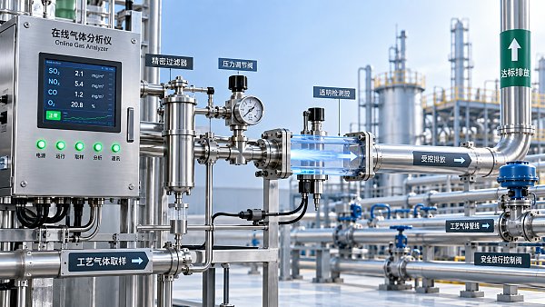
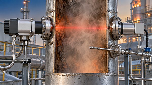
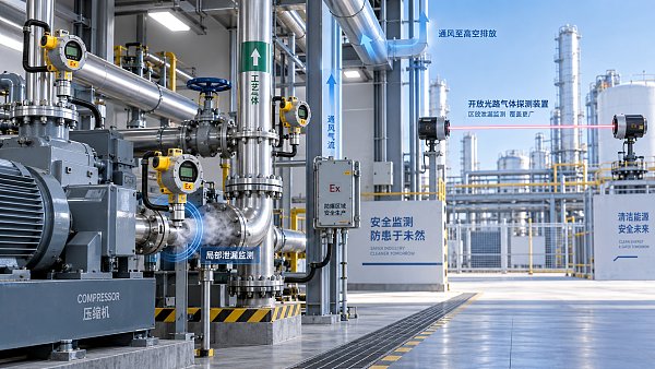
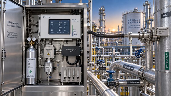
Laser analyzers are available in extractive and in-situ arrangements. Neither is universally superior. An in-situ cross-stack or probe installation avoids transport delay and can provide rapid response, but its optical path is exposed to dust, condensate, vibration, alignment changes, temperature gradients, and deposits on windows. An extractive system permits controlled conditioning and a more protected optical cell, while adding tubing, filters, pumps, temperature control, and possible adsorption or condensation losses.
Ask a prospective manufacturer to explain why its proposed architecture fits the stated duty. The explanation should refer to the gas matrix and physical installation, not simply repeat a product category.
- For a high-temperature duct with changing dust loading, examine optical-window purge arrangements, purge gas quality, alignment tolerance, signal diagnostics, and how fouling is detected before the reading becomes unreliable.
- For reactive or soluble gases in an extractive system, inspect the wetted materials, temperature control from sampling point to cell, line length, dead volume, and whether filters or condensate handling can selectively remove the target component.
- Where pressure varies with production cycles, establish whether pressure is directly measured and compensated, tightly regulated before analysis, or treated as a fixed operating assumption.
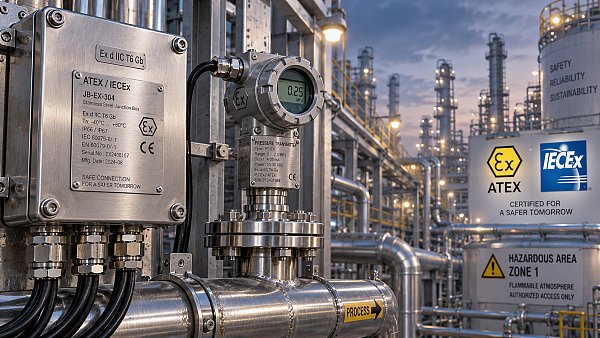
- For hazardous areas, separate the analyzer enclosure rating from the status of the complete installed system, including power, purge equipment, junction boxes, heated lines, and local interfaces.
Optical path length also needs context. A longer path can improve sensitivity for a weakly absorbing gas, yet it can increase exposure to beam attenuation, misalignment, and non-uniform gas conditions. A short path may be more robust in a dirty process but provide less signal at low concentration. Require a reasoned optical-path selection and request the operating limits for transmission, temperature, pressure, and background gas composition.
Interference assessment must be application-specific
Laser absorption is selective because the instrument targets a defined spectral absorption line, but selectivity is not absolute. Nearby absorption features from water vapor, carbon dioxide, methane, ammonia, or other process gases can affect the measurement. Pressure broadening, elevated temperature, and changing gas composition can alter the spectral shape enough to matter. A manufacturer that supplies an interference table without describing its relevance to the application has not completed the assessment.
Provide realistic maximum concentrations for all significant components, including substances expected during start-up, cleaning, regeneration, upset conditions, or fuel changes. Those temporary states are often absent from a normal-operation sample list, yet they may generate the largest optical interference or contaminate the sample system. Ask whether the analyzer fits a spectral model to distinguish gases, uses a reference channel, applies compensation, or requires the interfering component to remain within a specified bound.
Cross-sensitivity and physical sample loss are different problems. A cross-sensitivity error is caused by the optical measurement being affected by another gas. Sample loss occurs when the target gas reacts, dissolves, adsorbs, or condenses before reaching the measurement cell. The first is addressed through spectral validation and compensation; the second depends on materials, temperature, residence time, and conditioning design. Treating both under a generic “interference” heading can conceal an important installation risk.
Read specifications as a set, not as isolated numbers
Request raw definitions rather than relying on catalog labels. “Accuracy” can include different terms across suppliers: deviation from a reference, uncertainty under stated conditions, or an error limit after calibration. The distinction matters when comparing proposals. A sound technical submission identifies reference gas traceability where relevant, test conditions, averaging interval, warm-up period, and whether the value applies before or after field adjustment.
Data quality depends on diagnostics as much as nominal accuracy. Review transmitted-light monitoring, detector signal level, cell pressure and temperature status, laser-lock status, purge flow indication, sample flow, heated-line temperature, and fault behavior. Determine whether an invalid measurement is held, flagged, substituted, or sent as a numerical value. A plausible number without a quality flag can create more operational harm than an obvious failure.
Examine calibration and verification without assuming they are identical
Some laser analyzers are designed for long intervals between calibration because the wavelength-based measurement is inherently stable. That does not remove the need to verify the complete measurement chain. Deposits, changed optical transmission, sensor drift, pressure-control problems, altered sample transport, and reference gas handling can shift the operational result even when the laser source itself remains stable.
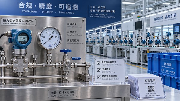
Clarify the distinction between factory calibration, field calibration, functional verification, and zero or span validation. For an in-situ system, field work may focus on optical alignment, window condition, purge performance, and a reference-path procedure rather than introducing calibration gas in the same way as an extractive analyzer. For an extractive system, the gas injection point is decisive. Introducing a test gas at the analyzer inlet checks the analyzer cell but bypasses the probe, heated line, filters, and conditioning equipment. Introducing it nearer the sample point tests more of the chain, though it may be harder to control.
Ask for recommended verification intervals as application guidance rather than accepting a single universal interval. A clean dry utility gas and a tar-bearing, high-moisture process stream impose different burdens. Also verify availability of suitable test gases, regulators, fittings, cylinders, and safe venting arrangements at the installation site. Calibration plans that cannot be executed safely during normal operation are rarely followed consistently.
Assess engineering evidence and configuration control
German manufacturing origin should not be used as a shortcut for technical suitability. Review evidence tied to the exact proposed configuration: optical head or cell, laser wavelength, gas range, sample-contact materials, enclosure, electronics, communications, and software revision. A product family may cover many gases and environments, while only a subset of configurations supports the duty under review.
Material selection is particularly important for corrosive, wet, or high-purity service. Stainless steel grades, seals, tubing polymers, filter media, optical-window materials, and coatings all need to withstand the gas mixture and temperature. Compatibility should cover cleaning chemicals and occasional upset gases, not only the nominal sample. Elastomer swelling, sulfur attack, chloride exposure, and adsorption on polymer tubing can produce delayed or misleading readings long before a complete failure occurs.
Request wiring diagrams, dimensional drawings, utility requirements, communication register documentation, alarm logic, maintenance instructions, and a defined acceptance procedure before final configuration. Interfaces with a PLC, DCS, historian, or safety system should identify scaling, units, update interval, failure state, time synchronization where needed, and the treatment of maintenance mode. An analog output alone may carry the concentration but omit diagnostic context; digital communication can expose richer status information, provided the integration mapping is documented.
Service capability is part of measurement reliability
Evaluate support through the tasks required after commissioning: remote fault diagnosis, optical alignment assistance, replacement of source or detector components, repair turnaround, software access, and availability of field personnel familiar with the application. The useful question is not whether support exists in general, but which party owns each activity and what evidence is needed to diagnose a problem remotely.
Spare-parts planning should distinguish consumables from components that affect calibration or alignment. Filters, seals, purge fittings, and sample pumps may require routine replacement. Optical windows, laser modules, detectors, pressure sensors, heated assemblies, and proprietary electronics raise different questions about lead time, exchange procedure, and post-replacement verification. Insist that critical spares are identifiable by part number and configuration, especially when a system has been customized for a gas range or hazardous-location arrangement.
Before selection, convert the application description into a short acceptance matrix and ask each candidate to respond against the same conditions. Include normal and abnormal gas composition, temperature and pressure envelope, moisture, dust, location classification, required response, data interface, verification method, and defined acceptance criterion. Differences between manufacturers then become visible in assumptions, exclusions, and engineering depth rather than being hidden behind non-comparable specification sheets.
Recommended for You
 How to verify accuracy claims for industrial quality analyzersVerify accuracy claims for industrial quality analyzers with calibration checks, independent testing, and clear acceptance criteria. Learn how to reduce risk and buy with confidence.
 How to calculate cooling loads for an industrial analyzer shelterSize industrial analyzer shelter cooling with confidence. Learn to calculate equipment heat, solar gains, and ventilation loads, then select HVAC capacity for reliable analyzer performance.
 Industrial Safety vs. Emission Monitoring: What Are the Differences?What are the main differences between industrial safety and emission monitoring? Compare goals, sensors, response times, and compliance needs to choose the right systems for your facility.
 Is Remote Monitoring Worth the Cost for Small Emission Sources?Is it worth investing in remote monitoring for small emission sources? Compare costs, compliance needs, and potential savings to choose the right solution for your operation.
 How Do You Handle Analyzer Failure During an Environmental Audit?Learn how to handle analyzer failure during environmental compliance audit procedures. Protect evidence, verify data, and restore monitoring with this practical response guide.
 Do VOC Monitors Require Explosion-Proof Certification?Does VOC monitoring require explosion-proof certification? Learn when approval is needed, compare ATEX and IECEx, and choose the right monitor for your site.
 How sample conditioning affects accuracy in petrochemical analyzersImprove accuracy in petrochemical analyzers with smarter sample conditioning. Discover how phase control, filtration, and transport design prevent bias and deliver reliable process data.
 How to troubleshoot sensor drift in industrial gas detectorsIndustrial gas detectors showing sensor drift? Learn how to verify calibration gas, identify root causes, and determine when sensor replacement is needed for reliable monitoring.
 How to judge whether a competitive price reflects real valueCompetitive Price: learn how to compare scope, compliance, performance, and lifecycle costs to identify real value, reduce risk, and make smarter purchasing decisions.
 When custom gas analysis is the right fit for complex process streamsCustom gas analysis for complex process streams: learn when tailored sampling, interference control, and reliable measurement design deliver confident decisions.
 When does a laser gas analyzer meet stack emissions monitoring needs?Laser gas analyzer for stack emissions: learn when it delivers fast, reliable data, how to assess installation risks, and what to verify for CEMS compliance.
 How to select a hazardous gas analyzer for confined spacesHazardous gas analyzer selection for confined spaces: compare sensors, sampling, certifications, alarms, and maintenance to protect workers and choose with confidence.
 When is a single gas analyzer sufficient for workplace safety monitoring?Discover when a single gas analyzer delivers reliable workplace safety monitoring, and learn the key limits, calibration needs, and risks that require broader detection.
 How to choose an ambient gas analyzer for low-level leak detectionAmbient gas analyzer selection for low-level leak detection: compare sensitivity, cross-sensitivity, sampling design, alarms, and calibration for reliable site performance.
 How to tell when an oxygen sensor needs replacementOxygen sensor replacement signs explained: learn how live data, fault codes, wiring checks, and exhaust inspections pinpoint the real issue before you buy.
 How laser gas analyzers improve combustion control in steel furnacesLaser gas analyzer for steel industry applications delivers fast in-situ O₂ and CO data to optimize furnace combustion, cut fuel waste, and improve steel heating stability.
 How to verify whether explosion proof equipment meets site requirementsExplosion proof equipment verification made practical: match zones, gas or dust groups, temperature classes, certificates, and installation conditions for confident compliance.
 How industrial gas analysis helps detect contamination before releaseIndustrial Gas Analysis helps detect moisture, oil, oxygen, and toxic contaminants before release—protecting processes, ensuring compliance, and reducing costly risks.
 When is electrochemistry detection the right choice for water analysis?Electrochemistry detection for water analysis: learn when fast, reliable monitoring of ions, chlorine, pH, and more delivers actionable results.
 How industrial standards reduce quality risks in supplier selectionIndustrial Standard guidance helps quality and safety managers reduce supplier risks, verify compliance, strengthen traceability, and build resilient instrumentation supply chains.
 When does a multi-component system reduce installation complexity?Multi component systems reduce installation complexity when they eliminate field interfaces, streamline commissioning, and provide proven compatibility. Learn how to assess total cost and supplier accountability.
 How to size an industrial control shelter for outdoor equipmentIndustrial control shelter sizing guide: optimize layout, HVAC, access, safety, and expansion space for reliable outdoor equipment operations.
 How flue analysis helps verify combustion efficiencyFlue analysis verifies combustion efficiency by assessing O2, CO, CO2, and stack temperature to identify excess air, incomplete combustion, and heat losses.
 How to select industrial gas detectors for confined spacesIndustrial gas detectors for confined spaces: learn how to match sensors, sampling methods, alarms, and certifications to real atmospheric hazards.
 When does a laser oxygen analyzer outperform zirconia sensors?Laser oxygen analyzer vs. zirconia sensors: compare speed, selectivity, maintenance, gas chemistry, and installation needs to choose the right oxygen measurement solution.
 How to select a percent range analyzer for process measurementsPercent range analyzer selection made practical: compare accuracy, sample systems, calibration, gas matrix, integration, and lifecycle cost for reliable process measurements.
 How explosion proof analysis verifies safe equipment for hazardous areasExplosion proof analysis verifies hazardous-area equipment by matching certifications, temperature ratings, installation details, and inspection controls for safer compliance.
 When does fixed gas detection need point sensors instead of open-path monitoring?Fixed gas detection: discover when point sensors outperform open-path monitoring for predictable leaks, enclosed zones, local alarms, and safer design decisions.
 How to choose industrial metrology systems for tight-tolerance partsIndustrial metrology guide for tight-tolerance parts: compare CMMs, optical scanners, gauges, uncertainty, workflow, and traceable inspection strategies.
 How process metrology reduces measurement variation in productionProcess metrology reduces production measurement variation by improving traceability, uncertainty control, calibration, and reliable quality decisions.
 How to select an industrial monitoring analyzer for harsh environmentsIndustrial monitoring analyzer selection for harsh environments: evaluate sampling, durability, hazardous-area compliance, accuracy, maintenance, and data reliability.
 How calibration intervals affect test and measurement equipment accuracyTest and measurement equipment calibration intervals directly affect accuracy, risk, compliance, and uptime. Learn how to set evidence-based schedules that protect critical decisions.


Search Categories
Search Categories
- Smart Meters & Power Quality
- Transformer Gas Analyzers
- BESS Thermal Runaway Detectors
- Energy, Power & Smart Grid Monitoring
- Optical Profilers & CMM
- Ultrasonic & X-Ray NDT
- Calibration Standards
- Precision Metrology & NDT
- Water Quality Analyzers
- CEMS & VOCs Monitors
- Price Trends
- Import & Export Updates
- Market Trends
- Industry News
- Industry Insights
Latest Article
- How to verify accuracy claims for industrial quality analyzersVerify accuracy claims for industrial quality analyzers with calibration checks, independent testing, and clear acceptance criteria. Learn how to reduce risk and buy with confidence.Posted by:
- How to calculate cooling loads for an industrial analyzer shelterSize industrial analyzer shelter cooling with confidence. Learn to calculate equipment heat, solar gains, and ventilation loads, then select HVAC capacity for reliable analyzer performance.Posted by:
- Industrial Safety vs. Emission Monitoring: What Are the Differences?What are the main differences between industrial safety and emission monitoring? Compare goals, sensors, response times, and compliance needs to choose the right systems for your facility.Posted by:
Please give us a message