Condensation in a CO2 analyzer sampling system can cause unstable readings, restrict sample flow, and damage sensitive components. Prevention starts with controlling moisture throughout the sampling path.
The practical rule is simple: keep the sample above its local dew point, or remove moisture under controlled conditions before it reaches the analyzer.
Choose between heated sampling and controlled drying according to the analyzer’s temperature limits, moisture tolerance, and required reporting basis. Insulation alone cannot guarantee protection.
This guide explains how operators can locate cold spots, select conditioning equipment, and verify reliable measurements without introducing avoidable errors through water removal or temperature changes.
Where does condensation actually start?
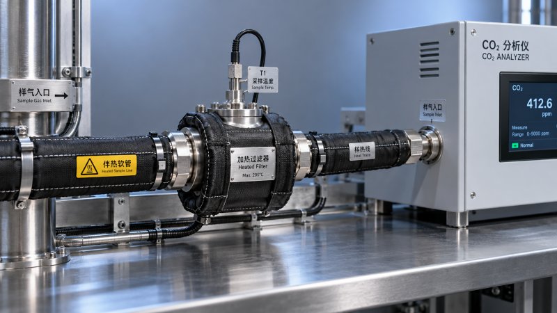
Condensation begins when a surface touching the sample falls below the water dew point at that location. Ambient temperature alone does not determine the risk.
A warm sample can therefore condense inside a cool fitting, even when most of the tubing feels hot and the analyzer enclosure appears adequately heated.
Common trouble spots include probe outlets, unheated filters, exposed valves, cabinet penetrations, pump heads, and the short connection between a heated line and analyzer inlet.
Water content and absolute pressure determine the dew point. Changes in operating pressure can change condensation risk, so assess conditions where each component actually operates.
Check startup, shutdown, low ambient temperatures, and maximum process moisture. A system that stays dry during normal afternoon operation may become wet overnight or during restart.
Visible droplets confirm a problem, but their absence proves little. Thin moisture films inside tubing or filters can disrupt measurements before operators see collected water.
Should you keep the sample hot or remove its moisture?
Start with the CO2 analyzer manual and the measurement requirement. Confirm permitted inlet temperature, pressure, flow, humidity, and whether results must represent wet or dry gas.
These requirements determine the conditioning strategy. Heating and drying can both prevent liquid water, but they produce different sample conditions and require different operating checks.
Hybrid systems often heat the transport line, then cool the sample inside a conditioning cabinet. This prevents uncontrolled condensation before water reaches the intended removal point.
Do not assume that every infrared CO2 analyzer accepts saturated gas. Humidity compensation addresses specified measurement effects; it does not automatically make liquid water acceptable.
For regulated monitoring, follow the approved measurement method and system configuration. Changing a dryer or cooler may affect reporting validity even when readings look stable.
Set temperatures from dew point, not guesswork
Determine the highest expected water dew point using process moisture data, suitable humidity measurements, or an engineering calculation at the relevant absolute pressure during operation.
For illustration, gas containing 10% water vapor by volume at approximately atmospheric pressure has a water dew point near 46°C. Pressure changes alter that value.
A line set to 40°C would allow that sample to condense. The appropriate setting must exceed the expected dew point while respecting every component’s temperature rating.
Use a documented temperature margin that accounts for control accuracy, ambient changes, and cold spots. There is no universally correct heating margin for every installation.
Check actual temperatures at vulnerable locations during representative operation. A controller measures its sensor location; it cannot prove that remote fittings or valves are warm enough.
Where acidic or condensable process components are present, assess their condensation limits separately. Keeping above the water dew point may not prevent corrosion or deposits.
Make heated lines protect the complete sampling path
Trace the route from extraction probe to analyzer cell. Include filters, manifolds, valves, regulators, pumps, and all connections when identifying components that need temperature control.
Short unheated sections deserve particular attention. A metal connector exposed to cold air can collect water despite being attached to an otherwise correctly heated hose.
Use heating and insulation designed for the installation, including hazardous-area requirements where applicable. Follow manufacturer instructions for bending, termination, sensor placement, and permitted operating temperatures.
Insulation slows heat loss but supplies no heat. It cannot keep a wet sample above its dew point indefinitely when surrounding temperatures remain too low.
Reduce unnecessary tubing length and dead legs where practical. Longer paths increase heat loss, response time, and the number of locations requiring inspection and maintenance.
Where the system design permits, interlock sample admission with heating readiness. Restore flow only after required components reach their operating temperatures and alarms are clear.
Operate coolers, separators, and drains as one system
A sample cooler deliberately condenses water at a controlled location. Its separator and drain must remove that liquid before the gas continues toward sensitive components.
Size the cooler for maximum sample flow, inlet temperature, moisture load, and ambient conditions. An undersized unit may maintain its display setting while delivering inadequate conditioning.
Check the manufacturer’s specified outlet dew point under those conditions. A cooling block temperature reading alone does not establish the moisture content of the delivered sample.
Keep downstream surfaces above the conditioned sample’s dew point. Gas leaving a cooler near saturation can condense again if downstream tubing becomes colder than the outlet.
Inspect drains for blockages, worn pump tubing, failed traps, and freezing. Under vacuum, unsuitable drain arrangements can admit air and dilute the measured CO2 concentration.
Install a carryover detector or protective shutoff where appropriate. A downstream filter can capture droplets temporarily, but it cannot replace effective cooling, separation, and drainage.
Plan for condensate disposal according to its composition and site procedures. Process condensate may contain corrosive or hazardous substances that require suitable materials and handling.
Avoid changing the CO2 result while removing water
Drying changes the concentration denominator because water vapor occupies part of the original gas volume. A higher dry reading does not necessarily indicate increased process CO2.
For example, a sample containing 10% CO2 and 10% water vapor on a wet basis contains approximately 11.1% CO2 after complete water removal, assuming conservation.
Using mole fractions, the relationship is CO2(dry) = CO2(wet) ÷ [1 − H2O(wet)]. Apply it only when the moisture fraction and reporting basis are established.
A refrigerated cooler usually leaves residual water vapor. Treating its outlet as completely dry can introduce additional error unless the measurement procedure accounts for that moisture.
CO2 can also dissolve in collected condensate. The resulting bias depends on operating conditions, including liquid contact, temperature, and chemistry; minimize unnecessary gas–liquid contact time.
Membrane dryers and other conditioning devices also require application checks. Verify CO2 recovery and response under representative humidity, pressure, and flow rather than assuming perfect selectivity.
For critical measurements, challenge the complete sampling system using an appropriate validation procedure. Dry calibration gas delivered directly to the analyzer cannot establish humid-sample conditioning performance.
What should operators check when readings become unstable?
First compare the analyzer response with sample flow, pressure, heating status, cooler performance, and ambient conditions. Their timing often helps distinguish condensation from genuine process variation.
If liquid has reached the analyzer, stop sample admission according to the operating procedure. Isolate and depressurize equipment safely before opening filters, drains, or connections.
Remove collected liquid and correct its source before restarting. Follow the manufacturer’s recovery procedure; do not assume that increasing heat or flow will safely dry everything.
After recovery, verify leak tightness, operating conditions, and analyzer performance. Use complete-system checks where needed, because calibration alone cannot confirm that the sampling path is functioning.
Build condensation prevention into routine operating checks
At startup, confirm heating readiness, cooler status, drainage, sample flow, and pressure before accepting measurements. Apply the site’s required stabilization and data-validity criteria during warmup.
During routine rounds, inspect accessible tubing, filter bowls, and drain operation. Review alarms and temperature trends instead of relying only on the current analyzer reading.
Set maintenance intervals from actual service conditions and manufacturer guidance. High particulate loading, heavy moisture, freezing weather, or corrosive condensate can justify more frequent inspections.
After replacing tubing, filters, pumps, or dryers, check whether pressure, temperature, flow, or moisture removal changed. Small component substitutions can affect the complete system’s behavior.
Record the operating envelope: expected dew point, heating limits, cooler performance, flow range, and reporting basis. Clear records help operators recognize deviations before liquid reaches the analyzer.