What Are the Common Pitfalls of Integrating Multiple Gas Analyzers?


Integrating multiple gas analyzers can improve process visibility, emissions reporting, safety monitoring, and product-quality control—but only if the analyzers function as a coherent measurement system rather than as separate instruments sharing a control room. The most damaging failures are rarely caused by an analyzer’s headline specification. They usually arise at the interfaces: sample transport, conditioning, calibration philosophy, timing, signal handling, and responsibility boundaries between suppliers.
A system may contain reliable oxygen, CO, CO2, NOx, SO2, methane, hydrogen sulfide, moisture, or total hydrocarbon analyzers and still produce misleading conclusions if their measurements are not comparable in time, basis, range, or sample condition. This is the central answer to what are common pitfalls when integrating multiple gas analyzers: integration risk lies in the measurement chain, not merely in connecting devices to a network.
Why can analyzers disagree even when each instrument is operating normally?
Different analyzer technologies do not observe a gas stream in exactly the same way. Non-dispersive infrared (NDIR), paramagnetic, electrochemical, zirconia, tunable diode laser absorption spectroscopy (TDLAS), flame ionization detection (FID), chemiluminescence, gas chromatography, and mass spectrometry each respond to different physical or chemical properties. They also have different response times, cross-sensitivity profiles, operating conditions, maintenance needs, and calibration requirements.
For example, an in-situ oxygen probe may report a change within seconds at the process boundary, while an extractive CO analyzer receiving gas through a heated line, filter, cooler, and conditioning cabinet may report the same event substantially later. Both results may be technically correct, but treating them as simultaneous can lead to an incorrect combustion diagnosis or an inappropriate control action.
Disagreement can also result from different reporting bases. One analyzer may report dry gas concentration, while another reports wet gas concentration. One may apply oxygen correction for emissions reporting; another may show raw concentration. One result may be expressed in ppmv, another in mg/Nm3, and another as volume percent. Unless the system clearly records and consistently applies temperature, pressure, moisture, molecular weight, and reference oxygen assumptions, apparently conflicting data can be created by calculation rather than by the instruments themselves.
Is a shared sampling system always the best integration method?
No. A common sampling system can reduce duplicate hardware and simplify access, but it can also create a single point of failure and introduce measurement compromises. The sample path must preserve the properties that matter for every component being measured.
Condensable compounds, reactive gases, aerosols, particulate matter, and moisture make this especially important. Hydrogen chloride, ammonia, hydrogen sulfide, sulfur dioxide, nitrogen dioxide, and many volatile organic compounds can be affected by adsorption, dissolution, chemical reaction, or loss within unsuitable tubing, filters, coolers, pumps, and fittings. A conditioning arrangement designed to protect one analyzer can undermine another. Removing water through a chiller may be appropriate for a dry-basis measurement, but it may alter the concentration of water-soluble gases and make that sample unsuitable for certain regulatory or process applications.
Material selection is therefore not a minor procurement detail. Stainless steel, PTFE, PFA, SilcoNert-treated components, heated probes, and heated lines have different suitability depending on temperature, pressure, gas composition, and analytes of interest. Long unheated tubing can create condensation and adsorption problems even when the analyzer cabinet is well specified.
A shared probe also requires a realistic assessment of flow demand. If several analyzers draw from one sample source, pressure drops, bypass flow, switching valves, filters, and pump capacity must be engineered to maintain representative sampling. A low-flow analyzer added late to an existing manifold may appear harmless but can disturb flow balance or increase lag time across the entire system.
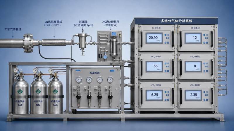
How does poor sampling design create false confidence?
Gas analysis begins at the extraction point, not at the analyzer. A precise instrument cannot correct a non-representative sample. Common design errors include locating the probe in a stratified duct section, selecting an extraction point too close to bends or dampers, ignoring particulate loading, or using a probe that cannot tolerate process temperature and velocity.
In flue gas, combustion exhaust, refinery streams, and chemical process lines, composition may vary across the pipe or duct. The sample point must reflect the parameter being controlled or reported. A probe placed where dilution air enters, where condensation occurs, or where deposits accumulate can generate a stable but unrepresentative reading. Stability should not be mistaken for accuracy.
Transport delay is another frequent blind spot. Sample travel time depends on line length, internal diameter, pressure, temperature, flow rate, and the volume of filters, conditioners, and analyzer cells. If the system includes multiplexing—one analyzer sequentially measuring several streams—the delay is longer and must include purge time after every stream change. Without validated timing, a data historian may assign a reading to the wrong operating period or even the wrong sample point.
The same concern applies to fast process upsets. A multi-analyzer package that identifies a release, combustion excursion, or product contamination event after the control opportunity has passed may still be useful for investigation, but it is not suitable as the primary control input.
What communication and data-integration issues are most often underestimated?
Connecting analyzers through Modbus, Profibus, Foundation Fieldbus, Ethernet/IP, OPC UA, or a vendor-specific interface does not guarantee usable data integration. Protocol compatibility is only the first layer. The control system must also understand what each tag represents, which unit applies, whether the value is raw or corrected, how quality status is encoded, and what happens during calibration, maintenance, warm-up, fault, or range switching.
A numerical value without context is particularly dangerous. A value of 50 can mean 50 ppm, 50 ppb, 50 mg/Nm3, 50% of range, or a diagnostic placeholder. Some instruments transmit a last valid value during a fault; others transmit a defined error code; others may force an output upscale or downscale. If the distributed control system (DCS), supervisory control and data acquisition (SCADA) platform, or environmental data acquisition system interprets these states inconsistently, alarms and reports can become unreliable.
Time synchronization deserves equal attention. Analyzer clocks, PLCs, data loggers, and historian servers should use a controlled time source such as Network Time Protocol (NTP) or Precision Time Protocol (PTP) where the application requires tighter synchronization. The required precision depends on the process. A slow-moving ambient monitoring application may tolerate wider alignment than combustion optimization, batch processing, or incident reconstruction. What matters is that timestamps represent the actual measurement event after known sample transport and processing delays are accounted for.
Integration specifications should define tag naming, units, decimal precision, bad-data behavior, calibration-state indicators, alarm priorities, event logs, time source, cybersecurity responsibilities, and ownership of configuration files. These details are frequently left to site commissioning, when changes are more expensive and responsibilities are less clear.
Why does calibration become harder as more analyzers are added?
Calibration is not simply a periodic check that each analyzer produces a plausible reading. In a multi-analyzer system, calibration must establish traceability and comparability across all measurements used in the same decision. If oxygen, CO, NOx, and hydrocarbons are evaluated together to tune combustion, their calibration status, zero quality, span gas uncertainty, response behavior, and maintenance condition affect the interpretation of the complete dataset.
Different analyzer technologies may require different zero gases, span gases, calibration intervals, and acceptance criteria. Some applications require certified reference materials with traceability appropriate to the governing quality or regulatory framework. Calibration gas concentration must also suit the analyzer range and intended measurement point. A span point that is too close to zero provides limited confidence at elevated process concentrations; a span point far above normal operation may conceal low-level performance problems.
Cross-sensitivity is often overlooked during calibration because a clean calibration gas does not reproduce the real process matrix. An analyzer may respond acceptably to its target gas under laboratory conditions but show interference from water vapor, CO2, sulfur compounds, background hydrocarbons, pressure changes, or temperature variation in service. Compensation algorithms can help, but they depend on valid assumptions and, in some cases, accurate input from another analyzer. This creates hidden dependencies: a drifting moisture or CO2 measurement can affect the corrected result of a different channel.
Calibration records should distinguish analyzer drift from sampling-system effects. If a zero check fails, the cause may be optical contamination or sensor aging, but it may also be leakage, contaminated zero gas, a valve problem, a blocked filter, or residual process gas trapped in the sample line. Replacing an analyzer without resolving the sample-path fault only restarts the failure cycle.
Can analyzer ranges and detection limits be mixed without consequence?
They can be mixed, but the integration design must reflect the intended decision. A low-level emissions measurement, a safety alarm, and a process-control signal may require different ranges for the same gas. An instrument selected for broad coverage may have insufficient resolution near a compliance threshold. Conversely, a highly sensitive analyzer can saturate or require excessive dilution when exposed to normal process concentrations.
Automatic range switching introduces another complication. During a range transition, resolution, uncertainty, alarm behavior, and data continuity may change. The DCS or reporting platform needs to know which range was active and whether the value should be flagged. Blending data from multiple ranges without recording the active range can create artificial trends.
Detection limit should not be treated as the same as usable operating capability. The practical limit depends on noise, sample stability, matrix effects, calibration quality, response time, and required confidence. For compliance or safety applications, the relevant question is whether the entire measurement system can demonstrate performance at the decision threshold under expected operating conditions.
What safety and compliance gaps emerge during integration?
Analyzer integration can affect hazardous-area classification, functional safety, emissions reporting, and occupational exposure management. Electrical equipment, enclosures, cable glands, purge systems, heated components, sample pumps, and calibration connections must be assessed as a complete installation. An analyzer certified for a hazardous location does not automatically make every associated subsystem suitable for that location. ATEX and IECEx requirements, where applicable, concern the installed arrangement as well as equipment certification.
Sample systems themselves can present hazards. Extracting toxic, flammable, corrosive, or high-temperature gas creates risks at probes, drains, vents, relief paths, calibration connections, and maintenance points. Venting arrangements must not allow hazardous gas accumulation, cross-contamination, or unintended discharge into occupied areas. Isolation and depressurization provisions should be practical for maintenance, not merely present on a drawing.
For regulated emissions monitoring, a measurement chain may be subject to jurisdiction-specific methods, quality-assurance procedures, performance specifications, reporting rules, and record-retention obligations. It is unsafe to assume that a process analyzer can be repurposed for compliance monitoring solely because it measures the same gas. The required certification, calibration practice, data availability, redundancy, and audit trail may differ materially.
Where do procurement and project scopes commonly fail?
Many integration problems begin in the request for quotation. A specification may list gases, ranges, and communication protocols but omit process pressure, temperature, moisture, dust loading, background composition, hazardous-area classification, sample-point geometry, response-time requirement, utilities, ambient conditions, and maintenance access. Suppliers then quote against different assumptions, making price comparisons misleading.
Another recurring weakness is fragmented responsibility. One party supplies analyzers, another supplies the sample conditioning system, another builds the shelter, another integrates the PLC, and another is responsible for commissioning. Unless interface ownership is documented, critical tasks can be missed: heat tracing termination, drain management, sample-line pressure testing, signal scaling, alarm configuration, calibration-gas connections, cybersecurity settings, and final loop checks.
Factory acceptance testing can identify configuration defects before shipment, but it cannot fully validate a system without representative site conditions. Site acceptance should verify sample integrity, actual transport delay, analyzer response, calibration sequence, alarm actions, data flags, time synchronization, fail-safe behavior, and the consistency of values reaching the historian or reporting platform. Acceptance criteria should address system-level performance rather than treating each analyzer as an isolated package.
What should be resolved before equipment is ordered?
The most useful pre-order document is a measurement philosophy that connects each gas measurement to a specific operational or compliance decision. It should state the target analyte, expected concentration range, gas matrix, sample location, required response time, reporting basis, accuracy need, availability expectation, alarm purpose, and maintenance constraints.
From that foundation, the integration design can determine whether measurements should be in-situ or extractive, whether streams can share conditioning hardware, which components require heated handling, how moisture will be treated, which tags must be synchronized, and which analyzer states must invalidate or qualify downstream calculations.
A robust multi-analyzer system does not require every instrument to use the same technology, supplier, or calibration interval. It requires the differences to be explicit and controlled. When sampling, timing, data semantics, calibration, and site responsibilities are engineered together, multiple analyzers can provide a defensible view of the process. When those interfaces are assumed rather than specified, the system can create a larger volume of data while reducing confidence in the decisions based on it.
Recommended for You
 How to verify accuracy claims for industrial quality analyzersVerify accuracy claims for industrial quality analyzers with calibration checks, independent testing, and clear acceptance criteria. Learn how to reduce risk and buy with confidence.
 How to calculate cooling loads for an industrial analyzer shelterSize industrial analyzer shelter cooling with confidence. Learn to calculate equipment heat, solar gains, and ventilation loads, then select HVAC capacity for reliable analyzer performance.
 Industrial Safety vs. Emission Monitoring: What Are the Differences?What are the main differences between industrial safety and emission monitoring? Compare goals, sensors, response times, and compliance needs to choose the right systems for your facility.
 Is Remote Monitoring Worth the Cost for Small Emission Sources?Is it worth investing in remote monitoring for small emission sources? Compare costs, compliance needs, and potential savings to choose the right solution for your operation.
 How Do You Handle Analyzer Failure During an Environmental Audit?Learn how to handle analyzer failure during environmental compliance audit procedures. Protect evidence, verify data, and restore monitoring with this practical response guide.
 Do VOC Monitors Require Explosion-Proof Certification?Does VOC monitoring require explosion-proof certification? Learn when approval is needed, compare ATEX and IECEx, and choose the right monitor for your site.
 How sample conditioning affects accuracy in petrochemical analyzersImprove accuracy in petrochemical analyzers with smarter sample conditioning. Discover how phase control, filtration, and transport design prevent bias and deliver reliable process data.
 How to troubleshoot sensor drift in industrial gas detectorsIndustrial gas detectors showing sensor drift? Learn how to verify calibration gas, identify root causes, and determine when sensor replacement is needed for reliable monitoring.
 How to judge whether a competitive price reflects real valueCompetitive Price: learn how to compare scope, compliance, performance, and lifecycle costs to identify real value, reduce risk, and make smarter purchasing decisions.
 When custom gas analysis is the right fit for complex process streamsCustom gas analysis for complex process streams: learn when tailored sampling, interference control, and reliable measurement design deliver confident decisions.
 When does a laser gas analyzer meet stack emissions monitoring needs?Laser gas analyzer for stack emissions: learn when it delivers fast, reliable data, how to assess installation risks, and what to verify for CEMS compliance.
 How to select a hazardous gas analyzer for confined spacesHazardous gas analyzer selection for confined spaces: compare sensors, sampling, certifications, alarms, and maintenance to protect workers and choose with confidence.
 When is a single gas analyzer sufficient for workplace safety monitoring?Discover when a single gas analyzer delivers reliable workplace safety monitoring, and learn the key limits, calibration needs, and risks that require broader detection.
 How to choose an ambient gas analyzer for low-level leak detectionAmbient gas analyzer selection for low-level leak detection: compare sensitivity, cross-sensitivity, sampling design, alarms, and calibration for reliable site performance.
 How to tell when an oxygen sensor needs replacementOxygen sensor replacement signs explained: learn how live data, fault codes, wiring checks, and exhaust inspections pinpoint the real issue before you buy.
 How laser gas analyzers improve combustion control in steel furnacesLaser gas analyzer for steel industry applications delivers fast in-situ O₂ and CO data to optimize furnace combustion, cut fuel waste, and improve steel heating stability.
 How to verify whether explosion proof equipment meets site requirementsExplosion proof equipment verification made practical: match zones, gas or dust groups, temperature classes, certificates, and installation conditions for confident compliance.
 How industrial gas analysis helps detect contamination before releaseIndustrial Gas Analysis helps detect moisture, oil, oxygen, and toxic contaminants before release—protecting processes, ensuring compliance, and reducing costly risks.
 When is electrochemistry detection the right choice for water analysis?Electrochemistry detection for water analysis: learn when fast, reliable monitoring of ions, chlorine, pH, and more delivers actionable results.
 How industrial standards reduce quality risks in supplier selectionIndustrial Standard guidance helps quality and safety managers reduce supplier risks, verify compliance, strengthen traceability, and build resilient instrumentation supply chains.
 When does a multi-component system reduce installation complexity?Multi component systems reduce installation complexity when they eliminate field interfaces, streamline commissioning, and provide proven compatibility. Learn how to assess total cost and supplier accountability.
 How to size an industrial control shelter for outdoor equipmentIndustrial control shelter sizing guide: optimize layout, HVAC, access, safety, and expansion space for reliable outdoor equipment operations.
 How flue analysis helps verify combustion efficiencyFlue analysis verifies combustion efficiency by assessing O2, CO, CO2, and stack temperature to identify excess air, incomplete combustion, and heat losses.
 How to select industrial gas detectors for confined spacesIndustrial gas detectors for confined spaces: learn how to match sensors, sampling methods, alarms, and certifications to real atmospheric hazards.
 When does a laser oxygen analyzer outperform zirconia sensors?Laser oxygen analyzer vs. zirconia sensors: compare speed, selectivity, maintenance, gas chemistry, and installation needs to choose the right oxygen measurement solution.
 How to select a percent range analyzer for process measurementsPercent range analyzer selection made practical: compare accuracy, sample systems, calibration, gas matrix, integration, and lifecycle cost for reliable process measurements.
 How explosion proof analysis verifies safe equipment for hazardous areasExplosion proof analysis verifies hazardous-area equipment by matching certifications, temperature ratings, installation details, and inspection controls for safer compliance.
 When does fixed gas detection need point sensors instead of open-path monitoring?Fixed gas detection: discover when point sensors outperform open-path monitoring for predictable leaks, enclosed zones, local alarms, and safer design decisions.
 How to choose industrial metrology systems for tight-tolerance partsIndustrial metrology guide for tight-tolerance parts: compare CMMs, optical scanners, gauges, uncertainty, workflow, and traceable inspection strategies.
 How process metrology reduces measurement variation in productionProcess metrology reduces production measurement variation by improving traceability, uncertainty control, calibration, and reliable quality decisions.
 How to select an industrial monitoring analyzer for harsh environmentsIndustrial monitoring analyzer selection for harsh environments: evaluate sampling, durability, hazardous-area compliance, accuracy, maintenance, and data reliability.
 How calibration intervals affect test and measurement equipment accuracyTest and measurement equipment calibration intervals directly affect accuracy, risk, compliance, and uptime. Learn how to set evidence-based schedules that protect critical decisions.
Search Categories
Search Categories
- Smart Meters & Power Quality
- Transformer Gas Analyzers
- BESS Thermal Runaway Detectors
- Energy, Power & Smart Grid Monitoring
- Optical Profilers & CMM
- Ultrasonic & X-Ray NDT
- Calibration Standards
- Precision Metrology & NDT
- Water Quality Analyzers
- CEMS & VOCs Monitors
- Price Trends
- Import & Export Updates
- Market Trends
- Industry News
- Industry Insights
Latest Article
- How to verify accuracy claims for industrial quality analyzersVerify accuracy claims for industrial quality analyzers with calibration checks, independent testing, and clear acceptance criteria. Learn how to reduce risk and buy with confidence.Posted by:
- How to calculate cooling loads for an industrial analyzer shelterSize industrial analyzer shelter cooling with confidence. Learn to calculate equipment heat, solar gains, and ventilation loads, then select HVAC capacity for reliable analyzer performance.Posted by:
- Industrial Safety vs. Emission Monitoring: What Are the Differences?What are the main differences between industrial safety and emission monitoring? Compare goals, sensors, response times, and compliance needs to choose the right systems for your facility.Posted by:
Please give us a message