
Combustible gas detection fails when sensors are misplaced


[Technical Procurement Intelligence Summary]:Combustible gas detection is only as reliable as the placement strategy behind it. A misplaced sensor can create a dangerous blind spot, weaken compliance, and turn a technically sound safety system into false assurance.
Reliable gas monitoring depends on gas behavior, ventilation patterns, ignition sources, process risk, and maintenance access. Sensor location is not an installation detail. It is a core engineering decision.
Why Combustible Gas Detection Needs a Placement Checklist
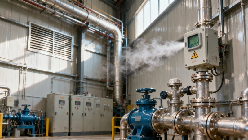
Combustible gas detection often fails silently. The system may pass power checks, transmit normal signals, and still miss a leak because the sensor is not in the gas path.
A checklist prevents assumptions from becoming design flaws. It forces each detector position to be justified by hazard evidence, not convenience.
Industrial sites change over time. New equipment, ducting, walls, or operating modes can alter airflow. A checklist helps keep combustible gas detection aligned with real conditions.
In instrumentation practice, measurement quality depends on location. Gas detectors follow the same rule as flow, pressure, temperature, and analytical instruments.
Core Checklist for Combustible Gas Detection Placement
Use this checklist before installation, during commissioning, and after any site modification. Each item should be documented with drawings, photographs, and risk notes.
- Identify credible leak sources first, including flanges, valves, compressors, pumps, seals, sample points, storage interfaces, and flexible connections.
- Map gas density against air, then place sensors where the gas will accumulate under realistic temperature and pressure conditions.
- Study ventilation direction during normal operation, shutdown, door opening, fan failure, and seasonal weather changes.
- Position detectors between likely leak points and ignition sources, especially near heaters, electrical panels, motors, and hot surfaces.
- Avoid dead zones behind structural columns, equipment skids, cable trays, ductwork, tanks, or large enclosures.
- Check whether dilution from strong airflow may prevent combustible gas detection from reaching alarm thresholds.
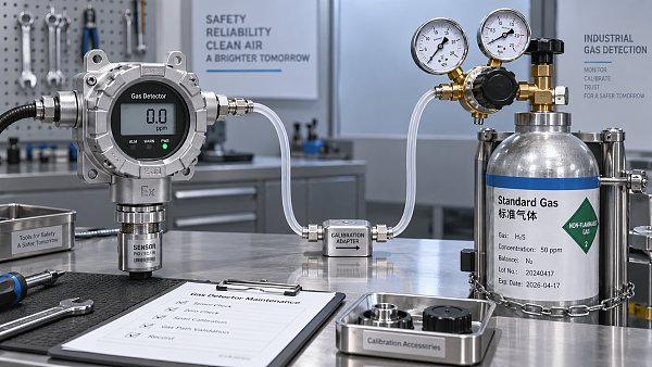
- Ensure access for bump testing, calibration, inspection, sensor replacement, and cleaning without unsafe workarounds.
- Protect sensors from water spray, dust loading, paint, steam, vibration, chemical poisoning, and mechanical impact.
- Confirm alarm setpoints match the gas type, lower explosive limit, site philosophy, and local regulatory expectations.
- Validate coverage with smoke tests, tracer gas studies, CFD modeling, or documented engineering judgement.
This checklist makes combustible gas detection defensible. It also creates a clear record for audits, insurance reviews, and incident investigations.
Understand Gas Behavior Before Choosing Sensor Height
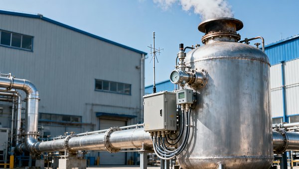
Sensor height is one of the most common reasons combustible gas detection underperforms. Light gases rise, heavy gases settle, and mixed gases may behave unpredictably.
Hydrogen and methane usually require higher placement. Propane, butane, gasoline vapor, and many solvent vapors often require lower placement.
However, density alone is not enough. Hot releases may rise first. Cold releases may sink. Pressurized jets may travel horizontally before dispersing.
Effective combustible gas detection considers release momentum, process temperature, vapor pressure, enclosure shape, and ventilation strength together.
Checklist for Sensor Height
- Review the target gas properties and confirm whether the detector should monitor ceiling space, breathing zone, or low-level accumulation points.
- Compare theoretical gas movement with actual airflow by observing smoke movement near leak-prone equipment.
- Place low-level detectors where pooling is credible, but keep them protected from flooding, washing, and forklift impact.
- Place high-level detectors where rising gas can collect, not where beams, ducts, or fans divert the plume.
Scenario Notes for Different Industrial Environments
Chemical Processing Areas
Chemical units often contain multiple gas families. Combustible gas detection should be mapped by process section, not treated as one uniform coverage zone.
Reactors, loading arms, solvent tanks, pumps, and transfer lines require separate review. Temporary maintenance openings can also create new leak points.
Oil, Gas, and Energy Facilities
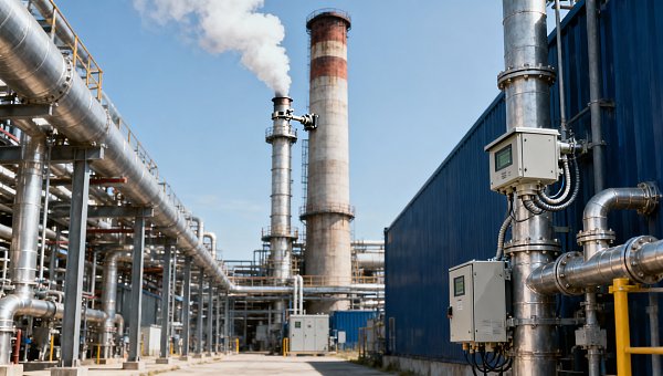
Well pads, compressor stations, LNG areas, and turbine enclosures need special attention to wind, release pressure, and equipment congestion.
Open-air combustible gas detection may need wider spacing, but spacing alone is not coverage. Detectors must still intercept likely plumes.
Battery Energy Storage and Power Rooms
Energy storage sites may face hydrogen, electrolyte vapor, or thermal runaway byproducts. Placement should support early warning before escalation.
Cabinet layout, forced ventilation, ceiling pockets, and exhaust paths strongly affect combustible gas detection performance in these rooms.
Laboratories and Pilot Plants
Small rooms can still create high-risk gas pockets. Fume hoods, gas cylinders, benches, and extraction systems change dispersion patterns.
Combustible gas detection should not be placed only at room entrances. It must reflect actual storage, use, and exhaust arrangements.
Commonly Ignored Risks That Cause Detection Failure
Ventilation changes after commissioning. Fan speed adjustments, blocked louvers, closed dampers, or added partitions can redirect gas away from installed detectors.
Sensor poisoning and contamination. Silicones, sulfur compounds, lead, solvents, dust, and oil mist can reduce sensor response without obvious visual damage.
Incorrect assumptions about open areas. Outdoor airflow does not guarantee safety. Wind shadows behind vessels and skids can hold hazardous gas pockets.
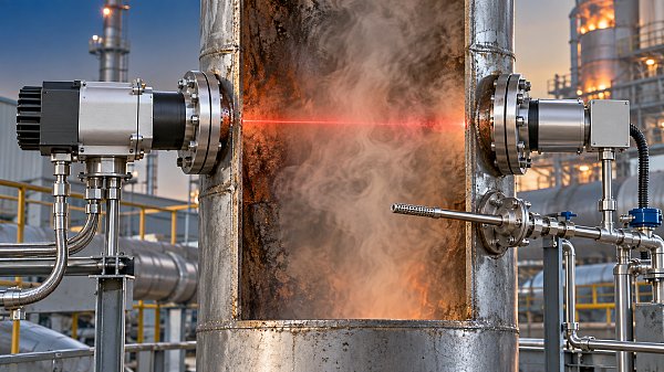
Overreliance on point detectors. Point combustible gas detection works only where gas reaches the sensing element. Open-path detection may support larger zones.
Maintenance access compromises. A detector placed correctly but unreachable may not be calibrated properly. Poor maintenance eventually becomes poor protection.
Alarm logic without process context. Alarm thresholds should consider shutdown timing, evacuation routes, ventilation interlocks, and escalation scenarios.
Practical Execution Guide for Reliable Combustible Gas Detection
Begin with a site walkdown. Mark leak sources, ignition sources, airflow direction, occupied areas, confined spaces, and escape routes on current drawings.
Then define detector objectives. Some locations need early leak warning. Others need shutdown confirmation, ventilation activation, or hazardous area protection.
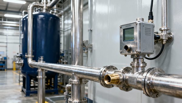
Next, compare detector technology. Catalytic bead, infrared, electrochemical, ultrasonic, and open-path devices each respond differently to gas and conditions.
- Use catalytic sensors where oxygen is present and poisoning risks are controlled through maintenance and gas selection checks.
- Use infrared sensors where hydrocarbon detection is needed and oxygen-independent measurement improves reliability.
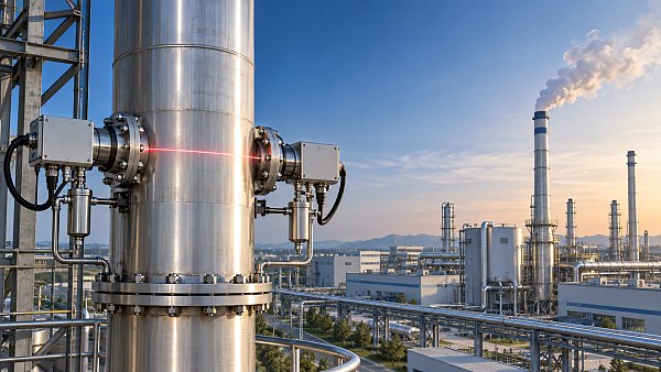
- Use open-path detectors across likely plume corridors, loading zones, or large process gaps with clear optical lines.
- Use ultrasonic gas leak detectors where high-pressure releases may disperse before concentration sensors alarm.
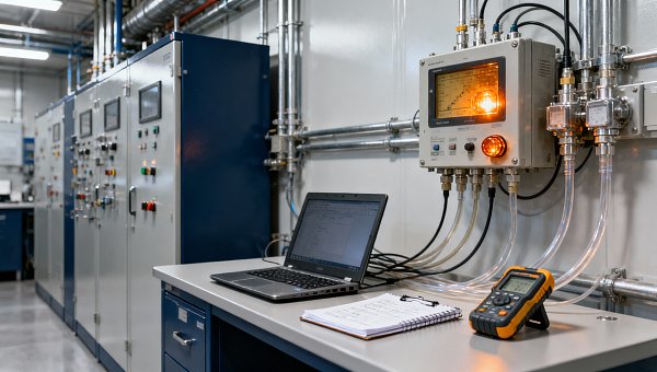
Commissioning should test more than signal continuity. Confirm detector response, alarm routing, shutdown logic, ventilation action, and human response procedures.
Periodic review is essential. Any process change, building change, ventilation change, or incident near miss should trigger a combustible gas detection reassessment.
Documentation That Supports Compliance and Trust
A strong documentation pack explains why each detector exists. It should connect every placement decision to risk, gas behavior, and operating conditions.
Useful records include hazard maps, detector layout drawings, calibration certificates, bump test logs, alarm matrices, and management of change approvals.
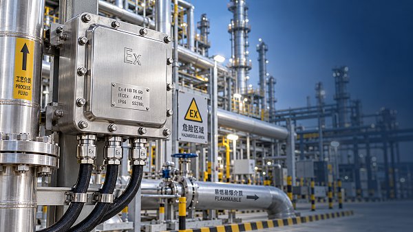
Where explosive atmospheres are possible, equipment selection should consider applicable certifications such as ATEX, IECEx, and local electrical codes.
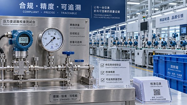
Instrumentation reliability also depends on traceable calibration. ISO/IEC 17025 practices can strengthen confidence in test gases and calibration services.
Final Action Checklist
- Audit existing combustible gas detection against current process drawings, not outdated installation assumptions.
- Verify that each sensor is located according to gas density, airflow, leak probability, and ignition risk.
- Test detector response under realistic maintenance procedures, including access, calibration, and alarm confirmation.
- Review ventilation behavior after equipment upgrades, enclosure changes, or seasonal operating adjustments.
- Document the rationale for every detector, including what hazard it covers and what action it initiates.
Combustible gas detection fails when sensors are placed for convenience instead of risk. A detector cannot alarm on gas it never encounters.
The next step is a placement review. Walk the site, challenge every detector location, and update the layout before blind spots become incidents.
Recommended for You
 How condensation affects stack detector readings in wet flue gasStack detector readings can drift when wet flue gas condenses. Learn how to identify moisture interference, prevent sample losses, and improve emissions monitoring reliability.
 How to prevent condensation in a CO2 analyzer sampling systemPrevent condensation in your CO2 analyzer sampling system. Learn how to control dew point, eliminate cold spots, and manage moisture for reliable readings and fewer costly disruptions.
 How to verify accuracy claims for industrial quality analyzersVerify accuracy claims for industrial quality analyzers with calibration checks, independent testing, and clear acceptance criteria. Learn how to reduce risk and buy with confidence.
 How to calculate cooling loads for an industrial analyzer shelterSize industrial analyzer shelter cooling with confidence. Learn to calculate equipment heat, solar gains, and ventilation loads, then select HVAC capacity for reliable analyzer performance.
 Do Regulatory Monitoring Systems Need Third-Party Certification?Do regulatory monitoring systems need third-party certification? Learn when it is required, what certificates prove, and how to verify compliance before buying.
 How Do You Choose Wired or Wireless for Stack Monitoring?Learn how to choose between wired and wireless for stack monitoring. Compare reliability, lifecycle costs, and data recovery to find the right CEMS setup for your site.
 What Happens When Combustible Gas Sensor Calibration Is Overdue?What happens if combustible gas sensor is not recalibrated on time? Discover the risks of inaccurate readings and missed alarms, plus steps to restore reliable protection.
 Can One Multi-Gas Detector Replace Four Separate Analyzers?Find out: can a single multi-gas detector replace four separate analyzers? Compare accuracy, safety, compliance, and lifetime costs to make a confident buying decision.
 Industrial Safety vs. Emission Monitoring: What Are the Differences?What are the main differences between industrial safety and emission monitoring? Compare goals, sensors, response times, and compliance needs to choose the right systems for your facility.
 Is Remote Monitoring Worth the Cost for Small Emission Sources?Is it worth investing in remote monitoring for small emission sources? Compare costs, compliance needs, and potential savings to choose the right solution for your operation.
 How Do You Handle Analyzer Failure During an Environmental Audit?Learn how to handle analyzer failure during environmental compliance audit procedures. Protect evidence, verify data, and restore monitoring with this practical response guide.
 Do VOC Monitors Require Explosion-Proof Certification?Does VOC monitoring require explosion-proof certification? Learn when approval is needed, compare ATEX and IECEx, and choose the right monitor for your site.
 How sample conditioning affects accuracy in petrochemical analyzersImprove accuracy in petrochemical analyzers with smarter sample conditioning. Discover how phase control, filtration, and transport design prevent bias and deliver reliable process data.
 How to troubleshoot sensor drift in industrial gas detectorsIndustrial gas detectors showing sensor drift? Learn how to verify calibration gas, identify root causes, and determine when sensor replacement is needed for reliable monitoring.
 How to judge whether a competitive price reflects real valueCompetitive Price: learn how to compare scope, compliance, performance, and lifecycle costs to identify real value, reduce risk, and make smarter purchasing decisions.
 When custom gas analysis is the right fit for complex process streamsCustom gas analysis for complex process streams: learn when tailored sampling, interference control, and reliable measurement design deliver confident decisions.
 When does a laser gas analyzer meet stack emissions monitoring needs?Laser gas analyzer for stack emissions: learn when it delivers fast, reliable data, how to assess installation risks, and what to verify for CEMS compliance.
 How to select a hazardous gas analyzer for confined spacesHazardous gas analyzer selection for confined spaces: compare sensors, sampling, certifications, alarms, and maintenance to protect workers and choose with confidence.
 When is a single gas analyzer sufficient for workplace safety monitoring?Discover when a single gas analyzer delivers reliable workplace safety monitoring, and learn the key limits, calibration needs, and risks that require broader detection.
 How to choose an ambient gas analyzer for low-level leak detectionAmbient gas analyzer selection for low-level leak detection: compare sensitivity, cross-sensitivity, sampling design, alarms, and calibration for reliable site performance.
 How to tell when an oxygen sensor needs replacementOxygen sensor replacement signs explained: learn how live data, fault codes, wiring checks, and exhaust inspections pinpoint the real issue before you buy.
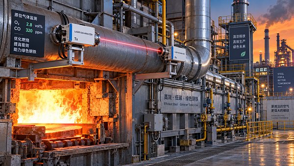
 How laser gas analyzers improve combustion control in steel furnacesLaser gas analyzer for steel industry applications delivers fast in-situ O₂ and CO data to optimize furnace combustion, cut fuel waste, and improve steel heating stability.
 How to verify whether explosion proof equipment meets site requirementsExplosion proof equipment verification made practical: match zones, gas or dust groups, temperature classes, certificates, and installation conditions for confident compliance.
 How industrial gas analysis helps detect contamination before releaseIndustrial Gas Analysis helps detect moisture, oil, oxygen, and toxic contaminants before release—protecting processes, ensuring compliance, and reducing costly risks.
 When is electrochemistry detection the right choice for water analysis?Electrochemistry detection for water analysis: learn when fast, reliable monitoring of ions, chlorine, pH, and more delivers actionable results.
 How industrial standards reduce quality risks in supplier selectionIndustrial Standard guidance helps quality and safety managers reduce supplier risks, verify compliance, strengthen traceability, and build resilient instrumentation supply chains.
 When does a multi-component system reduce installation complexity?Multi component systems reduce installation complexity when they eliminate field interfaces, streamline commissioning, and provide proven compatibility. Learn how to assess total cost and supplier accountability.
 How to size an industrial control shelter for outdoor equipmentIndustrial control shelter sizing guide: optimize layout, HVAC, access, safety, and expansion space for reliable outdoor equipment operations.
 How flue analysis helps verify combustion efficiencyFlue analysis verifies combustion efficiency by assessing O2, CO, CO2, and stack temperature to identify excess air, incomplete combustion, and heat losses.
 How to select industrial gas detectors for confined spacesIndustrial gas detectors for confined spaces: learn how to match sensors, sampling methods, alarms, and certifications to real atmospheric hazards.
 When does a laser oxygen analyzer outperform zirconia sensors?Laser oxygen analyzer vs. zirconia sensors: compare speed, selectivity, maintenance, gas chemistry, and installation needs to choose the right oxygen measurement solution.
 How to select a percent range analyzer for process measurementsPercent range analyzer selection made practical: compare accuracy, sample systems, calibration, gas matrix, integration, and lifecycle cost for reliable process measurements.



Search Categories
Search Categories
- Smart Meters & Power Quality
- Transformer Gas Analyzers
- BESS Thermal Runaway Detectors
- Energy, Power & Smart Grid Monitoring
- Optical Profilers & CMM
- Ultrasonic & X-Ray NDT
- Calibration Standards
- Precision Metrology & NDT
- Water Quality Analyzers
- CEMS & VOCs Monitors
- Price Trends
- Import & Export Updates
- Market Trends
- Industry News
- Industry Insights
Latest Article
- How condensation affects stack detector readings in wet flue gasStack detector readings can drift when wet flue gas condenses. Learn how to identify moisture interference, prevent sample losses, and improve emissions monitoring reliability.Posted by:
- How to prevent condensation in a CO2 analyzer sampling systemPrevent condensation in your CO2 analyzer sampling system. Learn how to control dew point, eliminate cold spots, and manage moisture for reliable readings and fewer costly disruptions.Posted by:
- How to verify accuracy claims for industrial quality analyzersVerify accuracy claims for industrial quality analyzers with calibration checks, independent testing, and clear acceptance criteria. Learn how to reduce risk and buy with confidence.Posted by:
Please give us a message
