
Thermal Measurement Accuracy: What Affects Real Readings


Accurate thermal measurement is not just a technical specification. It affects safety, process stability, product quality, maintenance timing, and confidence in operational decisions.
In real environments, temperature readings may drift because of placement, airflow, calibration, surface condition, electrical noise, or handling habits.
Understanding these influences helps separate a true temperature change from an instrument error, especially in demanding industrial, laboratory, energy, and facility scenarios.
Why Thermal Measurement Accuracy Changes by Scenario
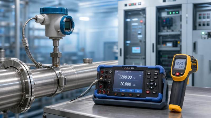
Thermal measurement looks simple when a display shows one number. In practice, that number is shaped by the environment around the sensor.
A reading inside a furnace, on a moving conveyor, or near a chilled pipeline can involve very different error sources.
The same thermometer can perform well in one location and poorly in another, even when it remains within specification.
Reliable thermal measurement therefore requires both suitable instrumentation and correct scenario judgment.
For Global Instrument Hub, this is a core instrumentation issue. Measurement data only becomes useful when uncertainty is understood.
Process Control Scenes Where Small Errors Become Big Risks
In chemical processing, food production, plastics, and metal treatment, thermal measurement supports stable recipes and safe operating limits.
A sensor placed away from the true heat zone may report a comfortable value while the product or vessel surface overheats.
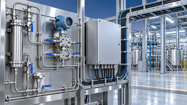
Thermowell design, immersion depth, fluid velocity, and sensor contact determine how closely the reading follows the actual process temperature.
Response time matters strongly in batch operations. Slow thermal measurement can hide rapid heating, cooling failure, or steam valve issues.
In high-pressure reactors, conservative setpoints are useful, but only when sensor accuracy and installation effects are already verified.
A practical judgment is simple. If temperature changes faster than the sensor responds, control decisions may lag behind reality.
Core Checks for Process Thermal Measurement
- Confirm immersion depth matches pipe diameter, velocity, and thermowell design.
- Compare sensor response time with expected process temperature change speed.
- Inspect deposits, scale, or fouling that can insulate the sensing point.
- Check whether vibration may loosen probes, fittings, or electrical connections.
Surface and Equipment Monitoring Scenes Need Contact Awareness
Motors, bearings, panels, pumps, and gearboxes are often checked through surface thermal measurement during maintenance routines.
These readings can indicate friction, overload, insulation failure, blocked airflow, or abnormal electrical resistance.
However, surface temperature is not always equal to internal component temperature. Housing thickness and heat transfer paths create delay.
Contact probes need stable pressure and enough dwell time. A rushed touch may capture the probe temperature, not the surface temperature.
Infrared thermal measurement adds another concern: emissivity. Shiny metal, painted surfaces, tape, oil, or dust can change apparent readings.
A consistent measurement point is essential. Moving a few centimeters may compare different heat paths, not different operating states.
Laboratory and Life Science Scenes Require Stability First
Laboratories depend on thermal measurement for incubators, freezers, water baths, sample storage, sterilization, and analytical preparation.
In these settings, accuracy is not only about one reading. Uniformity, stability, and traceability are equally important.
A chamber display may show the control sensor value, while samples experience a different temperature at another shelf level.
Door opening, loading density, fan performance, and sensor location all affect real thermal measurement results.
For cold-chain and biological storage, data logging intervals should match risk. Long gaps can miss short but damaging excursions.
Calibration should be traceable to recognized standards, especially when results support compliance, validation, or product release decisions.
Laboratory Judgment Points
- Measure at sample-relevant locations, not only near the controller probe.
- Map temperature distribution before relying on a single display value.
- Review logger accuracy, interval, battery status, and alarm delay settings.
- Keep calibration records aligned with ISO/IEC 17025 expectations when required.
Energy, Electrical, and Smart Grid Scenes Demand Noise Control
Power cabinets, transformers, battery systems, and renewable energy assets rely on thermal measurement for early fault detection.
Hot spots can signal loose connections, harmonic heating, overload, insulation aging, or battery thermal runaway risk.
Electrical environments also introduce electromagnetic interference. Poor shielding or grounding may distort low-level sensor signals.
Cable routing matters. Thermocouple and RTD lines should avoid high-current conductors, variable frequency drives, and switching equipment.
Infrared inspections should consider load condition. A lightly loaded circuit may appear normal despite a developing contact problem.
For batteries, multiple sensing points are better than one. Cell imbalance can create local heating before pack temperature rises.
Environmental and Building Scenes Are Shaped by Air Movement
HVAC systems, cleanrooms, warehouses, greenhouses, and environmental monitoring stations all need credible thermal measurement.
Air temperature changes quickly near vents, doors, windows, heat sources, and sunlit surfaces.
A sensor mounted on a warm wall can report wall influence instead of room air temperature.
Radiation shielding is important outdoors. Direct sunlight can heat the sensor body and create a false high reading.
Airflow can also cool probes unevenly. This affects thermal measurement when response time and installation shielding are ignored.
For storage areas, place sensors where goods actually sit. Ceiling-level data may not represent pallet-level conditions.
How Different Scenes Change Thermal Measurement Requirements
This comparison shows why thermal measurement accuracy cannot be judged by instrument specification alone.
The operating scene defines what must be controlled, verified, and documented.
Scenario-Based Practices That Improve Real Readings
Better thermal measurement starts with asking what the reading is expected to represent.
Is it fluid temperature, product temperature, surface temperature, air temperature, or a safety limit?
Once that target is clear, instrument selection and installation become more rational.
- Define the true measurement point before selecting the sensor type.
- Match accuracy class to process risk, not only purchase cost.
- Check response time under installed conditions, not only catalog conditions.
- Protect signal cables from electrical noise and thermal damage.
- Use calibration intervals based on drift history and operating severity.
- Record location, method, instrument ID, and environmental conditions.
These actions make thermal measurement results easier to compare across shifts, sites, and maintenance cycles.
Common Misjudgments That Create False Confidence
One common mistake is trusting a digital display because it has many decimal places.
Resolution is not accuracy. A display can show 0.1 degree while the installed uncertainty is much larger.
Another mistake is comparing two instruments without checking whether they measure the same physical point.
A probe in fluid, an infrared gun on a pipe, and a controller sensor may all show different valid values.
Calibration is also misunderstood. A calibrated instrument can still read incorrectly if installed in the wrong location.
Human handling matters too. Touching a probe, bending a thermocouple, or aiming at reflective metal can distort thermal measurement.
Maintenance teams should also watch for gradual drift. Small changes may appear harmless until they affect alarms or product quality.
Turning Thermal Measurement Data into Better Decisions
Reliable thermal measurement connects instruments, installation, calibration, environment, and operating context into one decision system.
When uncertainty is visible, temperature data becomes more than a number. It becomes a defensible control signal.
A useful next step is to review high-risk points first: safety limits, quality-critical zones, energy assets, and stored materials.
For each point, verify whether the measurement location, sensor type, calibration status, and environmental exposure still match current use.
Global Instrument Hub supports this disciplined approach through instrumentation intelligence, supplier research, and practical technical analysis.
By improving thermal measurement practices, operations gain safer control, clearer maintenance signals, and more trustworthy data for automation.
Start with one critical application, document the uncertainty sources, and standardize the method before expanding across the site.
Recommended for You
 How to prevent condensation in a CO2 analyzer sampling systemPrevent condensation in your CO2 analyzer sampling system. Learn how to control dew point, eliminate cold spots, and manage moisture for reliable readings and fewer costly disruptions.
 How to verify accuracy claims for industrial quality analyzersVerify accuracy claims for industrial quality analyzers with calibration checks, independent testing, and clear acceptance criteria. Learn how to reduce risk and buy with confidence.
 How to calculate cooling loads for an industrial analyzer shelterSize industrial analyzer shelter cooling with confidence. Learn to calculate equipment heat, solar gains, and ventilation loads, then select HVAC capacity for reliable analyzer performance.
 What Happens When Combustible Gas Sensor Calibration Is Overdue?What happens if combustible gas sensor is not recalibrated on time? Discover the risks of inaccurate readings and missed alarms, plus steps to restore reliable protection.
 Can One Multi-Gas Detector Replace Four Separate Analyzers?Find out: can a single multi-gas detector replace four separate analyzers? Compare accuracy, safety, compliance, and lifetime costs to make a confident buying decision.
 Industrial Safety vs. Emission Monitoring: What Are the Differences?What are the main differences between industrial safety and emission monitoring? Compare goals, sensors, response times, and compliance needs to choose the right systems for your facility.
 Is Remote Monitoring Worth the Cost for Small Emission Sources?Is it worth investing in remote monitoring for small emission sources? Compare costs, compliance needs, and potential savings to choose the right solution for your operation.
 How Do You Handle Analyzer Failure During an Environmental Audit?Learn how to handle analyzer failure during environmental compliance audit procedures. Protect evidence, verify data, and restore monitoring with this practical response guide.
 Do VOC Monitors Require Explosion-Proof Certification?Does VOC monitoring require explosion-proof certification? Learn when approval is needed, compare ATEX and IECEx, and choose the right monitor for your site.
 How sample conditioning affects accuracy in petrochemical analyzersImprove accuracy in petrochemical analyzers with smarter sample conditioning. Discover how phase control, filtration, and transport design prevent bias and deliver reliable process data.
 How to troubleshoot sensor drift in industrial gas detectorsIndustrial gas detectors showing sensor drift? Learn how to verify calibration gas, identify root causes, and determine when sensor replacement is needed for reliable monitoring.
 How to judge whether a competitive price reflects real valueCompetitive Price: learn how to compare scope, compliance, performance, and lifecycle costs to identify real value, reduce risk, and make smarter purchasing decisions.
 When custom gas analysis is the right fit for complex process streamsCustom gas analysis for complex process streams: learn when tailored sampling, interference control, and reliable measurement design deliver confident decisions.
 When does a laser gas analyzer meet stack emissions monitoring needs?Laser gas analyzer for stack emissions: learn when it delivers fast, reliable data, how to assess installation risks, and what to verify for CEMS compliance.
 How to select a hazardous gas analyzer for confined spacesHazardous gas analyzer selection for confined spaces: compare sensors, sampling, certifications, alarms, and maintenance to protect workers and choose with confidence.
 When is a single gas analyzer sufficient for workplace safety monitoring?Discover when a single gas analyzer delivers reliable workplace safety monitoring, and learn the key limits, calibration needs, and risks that require broader detection.
 How to choose an ambient gas analyzer for low-level leak detectionAmbient gas analyzer selection for low-level leak detection: compare sensitivity, cross-sensitivity, sampling design, alarms, and calibration for reliable site performance.
 How to tell when an oxygen sensor needs replacementOxygen sensor replacement signs explained: learn how live data, fault codes, wiring checks, and exhaust inspections pinpoint the real issue before you buy.
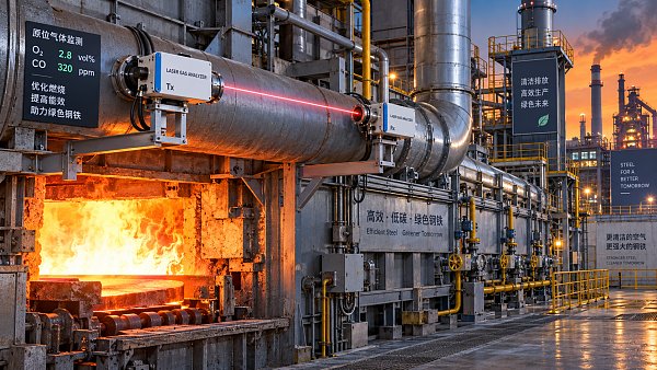
 How laser gas analyzers improve combustion control in steel furnacesLaser gas analyzer for steel industry applications delivers fast in-situ O₂ and CO data to optimize furnace combustion, cut fuel waste, and improve steel heating stability.
 How to verify whether explosion proof equipment meets site requirementsExplosion proof equipment verification made practical: match zones, gas or dust groups, temperature classes, certificates, and installation conditions for confident compliance.
 How industrial gas analysis helps detect contamination before releaseIndustrial Gas Analysis helps detect moisture, oil, oxygen, and toxic contaminants before release—protecting processes, ensuring compliance, and reducing costly risks.
 When is electrochemistry detection the right choice for water analysis?Electrochemistry detection for water analysis: learn when fast, reliable monitoring of ions, chlorine, pH, and more delivers actionable results.
 How industrial standards reduce quality risks in supplier selectionIndustrial Standard guidance helps quality and safety managers reduce supplier risks, verify compliance, strengthen traceability, and build resilient instrumentation supply chains.
 When does a multi-component system reduce installation complexity?Multi component systems reduce installation complexity when they eliminate field interfaces, streamline commissioning, and provide proven compatibility. Learn how to assess total cost and supplier accountability.
 How to size an industrial control shelter for outdoor equipmentIndustrial control shelter sizing guide: optimize layout, HVAC, access, safety, and expansion space for reliable outdoor equipment operations.
 How flue analysis helps verify combustion efficiencyFlue analysis verifies combustion efficiency by assessing O2, CO, CO2, and stack temperature to identify excess air, incomplete combustion, and heat losses.
 How to select industrial gas detectors for confined spacesIndustrial gas detectors for confined spaces: learn how to match sensors, sampling methods, alarms, and certifications to real atmospheric hazards.
 When does a laser oxygen analyzer outperform zirconia sensors?Laser oxygen analyzer vs. zirconia sensors: compare speed, selectivity, maintenance, gas chemistry, and installation needs to choose the right oxygen measurement solution.
 How to select a percent range analyzer for process measurementsPercent range analyzer selection made practical: compare accuracy, sample systems, calibration, gas matrix, integration, and lifecycle cost for reliable process measurements.
 How explosion proof analysis verifies safe equipment for hazardous areasExplosion proof analysis verifies hazardous-area equipment by matching certifications, temperature ratings, installation details, and inspection controls for safer compliance.
 When does fixed gas detection need point sensors instead of open-path monitoring?Fixed gas detection: discover when point sensors outperform open-path monitoring for predictable leaks, enclosed zones, local alarms, and safer design decisions.
 How to choose industrial metrology systems for tight-tolerance partsIndustrial metrology guide for tight-tolerance parts: compare CMMs, optical scanners, gauges, uncertainty, workflow, and traceable inspection strategies.
Search Categories
Search Categories
- Smart Meters & Power Quality
- Transformer Gas Analyzers
- BESS Thermal Runaway Detectors
- Energy, Power & Smart Grid Monitoring
- Optical Profilers & CMM
- Ultrasonic & X-Ray NDT
- Calibration Standards
- Precision Metrology & NDT
- Water Quality Analyzers
- CEMS & VOCs Monitors
- Price Trends
- Import & Export Updates
- Market Trends
- Industry News
- Industry Insights
Latest Article
- How to prevent condensation in a CO2 analyzer sampling systemPrevent condensation in your CO2 analyzer sampling system. Learn how to control dew point, eliminate cold spots, and manage moisture for reliable readings and fewer costly disruptions.Posted by:
- How to verify accuracy claims for industrial quality analyzersVerify accuracy claims for industrial quality analyzers with calibration checks, independent testing, and clear acceptance criteria. Learn how to reduce risk and buy with confidence.Posted by:
- How to calculate cooling loads for an industrial analyzer shelterSize industrial analyzer shelter cooling with confidence. Learn to calculate equipment heat, solar gains, and ventilation loads, then select HVAC capacity for reliable analyzer performance.Posted by:
Please give us a message
