How to choose industrial metrology tools for tight tolerances


Choosing industrial metrology tools for tight tolerances requires more than comparing resolution or specifications. Technical evaluators must consider measurement uncertainty, calibration traceability, environmental conditions, part geometry, and throughput to determine whether a system can reliably verify critical dimensions.
From coordinate measuring machines to optical instruments and precision gauges, each option has distinct capabilities and limitations. This guide explains the key selection criteria, helping you assess measurement performance, reduce inspection risk, and make confident procurement decisions.
What makes a metrology tool suitable for a tight tolerance?
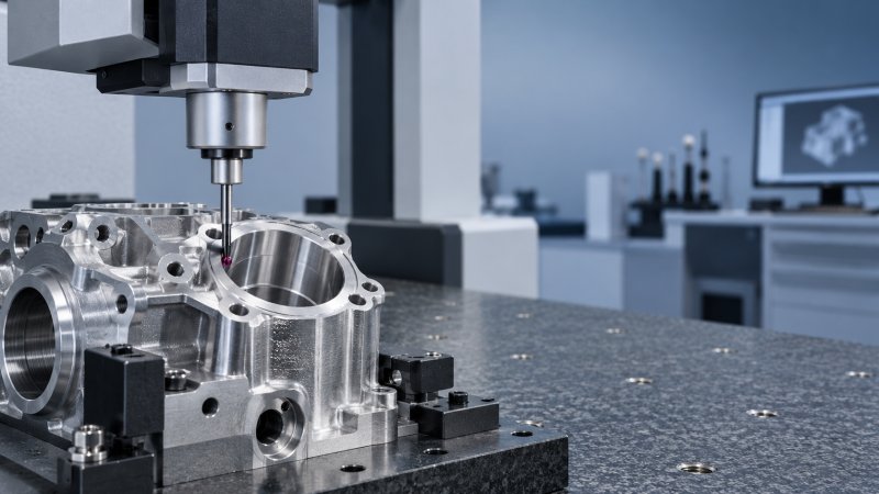
The best instrument is the one that can measure the specified characteristic with sufficiently low uncertainty under actual operating conditions, while meeting inspection time and cost requirements.
Start with the drawing or digital product definition. Identify the tolerance zone, datum references, inspection locations, surface requirements, and any contractual acceptance rules before comparing equipment.
A system that measures a diameter well may be unsuitable for verifying its position relative to multiple datums. Each characteristic needs its own measurement strategy.
Evaluate the complete measurement process, not just the instrument. Fixturing, probing, software algorithms, environmental variation, operator technique, and part condition all contribute to the result.
For a critical characteristic, ask the supplier to demonstrate performance on representative parts. A favorable catalog specification is a starting point, not proof of fitness for purpose.
How much measurement uncertainty can the tolerance allow?
Measurement uncertainty describes the range associated with a result within which the true value is expected to lie, at a stated level of confidence.
Compare expanded uncertainty with the full tolerance width, using the same units and a clearly stated coverage factor. Confirm that the estimate applies to your measurement task.
For example, a dimension specified as 20.000 mm ±0.010 mm has a 0.020 mm tolerance width. Expanded uncertainty of 0.002 mm represents 10% of that width.
That ratio can be a useful screening target, but it is not a universal acceptance criterion. Required performance depends on consequence of error, process capability, and customer agreements.
Also confirm whether a quoted ratio uses expanded uncertainty, another uncertainty measure, or equipment accuracy. Mixing definitions can make competing systems appear more comparable than they are.
Build an uncertainty budget that reflects calibration, repeatability, thermal effects, fixturing, geometry, probe interaction, and relevant software calculations. Account for correlations when they are significant.
Published maximum permissible errors, or MPEs, are instrument performance limits under specified test conditions. They are not automatically the uncertainty of measuring your actual part.
What decision rule will you use for pass or fail?
A measurement close to a specification limit creates decision risk: a conforming part can be rejected, or a nonconforming part can be accepted despite measurement uncertainty.
Agree on a decision rule before production inspection. Define the acceptance limits, treatment of uncertainty, rounding convention, and any guard band with the customer or quality authority.
A guard band moves the acceptance boundary inward from the specification limit. Its width should reflect the agreed risk model; it is not automatically equal to uncertainty.
Consider an upper limit of 20.010 mm and a guard band of 0.002 mm. Under that rule, the upper acceptance limit becomes 20.008 mm.
A result above 20.008 mm would not be accepted under that rule, even if it remains within the drawing limit. The lower limit needs its own treatment.
Review the impact on scrap, rework, and delivery performance. Better measurement capability may reduce the need for conservative acceptance limits, depending on the agreed decision rule.
Which industrial metrology tools fit the feature?
No single instrument is optimal for every measurement. Select a technology by characteristic, access, surface condition, required uncertainty, part size, and available cycle time.
A tactile CMM can verify complex relationships using contact points or scanning, but probe size, stylus deflection, accessibility, and measurement strategy affect the outcome.
Optical systems avoid contact forces and can capture many points quickly. Transparent, reflective, dark, or steep surfaces may require different lighting, sensors, or preparation.
For a single critical bore, a calibrated bore gauge with an appropriate setting standard may provide a faster and more economical solution than a full CMM program.
Surface finish requires its own method. A dimensional measurement system does not necessarily establish compliance with roughness parameters, filter settings, or sampling lengths specified on a drawing.
Where internal features are inaccessible, industrial computed tomography may be worth evaluating. Its suitability depends on material, part size, resolution, artifacts, and validated dimensional uncertainty.
How should you interpret instrument specifications?
Resolution is the smallest displayed or reported increment. It does not establish accuracy, repeatability, or uncertainty, so extra decimal places alone are not evidence of capability.
Repeatability indicates variation under specified repeated conditions. Reproducibility considers changed conditions, such as different operators or instruments; both matter when inspection is shared across shifts.
Check the conditions behind every accuracy or MPE claim: temperature, measurement length, probe configuration, orientation, loading, and the applicable test procedure can change the comparison.
For a CMM, request the relevant ISO 10360 acceptance and reverification results, including the tested configurations. Confirm that they cover the probes and operating range you intend to use.
For optical equipment, examine calibration field, magnification, working distance, edge-detection method, and performance across the full field of view, not only at its center.
Ask suppliers to distinguish factory acceptance data from installation performance. A machine that meets specifications at the factory still needs verification after delivery and commissioning.
Can your environment support the required performance?
Temperature changes affect both the instrument and the workpiece. Parts entering from a warm production process can produce misleading results even in a controlled inspection room.
Steel expands by roughly 11.5 micrometers per meter per degree Celsius. A 200 mm steel feature changes by approximately 2.3 micrometers for each degree Celsius change.
That change can consume a substantial share of a tight tolerance. The actual effect depends on material, geometry, temperature distribution, and any validated compensation method.
Define the reference temperature, typically 20 °C for dimensional specifications unless otherwise stated, and document stabilization time, temperature measurement locations, and allowable gradients.
Also assess vibration, airborne contamination, humidity where relevant, lighting, and power quality. Shop-floor instruments may offer protection or compensation, but those features still require validation.
Include fixtures and reference artifacts in the environmental assessment. Different materials and uneven heating can introduce relative movement that is not corrected by instrument compensation.
What calibration and traceability evidence should you request?
Metrological traceability requires a documented, unbroken calibration chain to a reference, with each calibration contributing to measurement uncertainty. A calibration sticker alone is insufficient evidence.
Request certificates that identify the instrument, calibration results, reference standards, measurement uncertainty, relevant conditions, and the calibration laboratory. Check coverage against your intended measurement range.
Where appropriate, use a laboratory accredited to ISO/IEC 17025 and verify that its accreditation scope covers the specific calibration service, range, and uncertainty you need.
Accreditation does not by itself prove that the instrument is fit for your application. Compare the certificate and instrument condition with the measurement task and acceptance criteria.
Set calibration intervals using manufacturer guidance, historical stability, usage, environment, and risk. Add intermediate checks with suitable artifacts to detect drift between scheduled calibrations.
Define what happens after an out-of-tolerance calibration: assess the affected period, investigate previous inspection decisions, contain potentially affected product, and document corrective action.
How do you validate performance before purchasing?
Provide shortlisted suppliers with representative parts, drawings, material details, surface conditions, and a ranked list of critical characteristics. Include difficult features, not only ideal samples.
Agree on the demonstration protocol beforehand: datum setup, fixture, measurement points, software settings, operator access, cycle time, and how results will be compared with a reference.
Use multiple parts spanning relevant dimensional variation. Repeated measurements of one stable artifact can reveal repeatability, but they do not demonstrate performance across the production range.
Run a measurement system analysis appropriate to the process, including repeatability and reproducibility where meaningful. A gauge R&R study complements, rather than replaces, uncertainty evaluation.
For automated systems, measure actual throughput from loading to result transfer. Include alignment, cleaning, changeover, exception handling, and any manual review in the cycle time.
Investigate disagreements between systems before attributing them to equipment accuracy. Different datum implementations, sampling strategies, filters, or algorithms may be measuring different interpretations of the feature.
Document the chosen configuration and acceptance criteria in the purchase specification. Require installation qualification, operator training, and a repeat demonstration at the intended operating location.
What should the procurement decision include?
Compare total ownership cost over the expected service life: equipment, probes, fixtures, software licenses, calibration, maintenance, environmental controls, training, and downtime all matter.
Check service response times, spare parts availability, support in your region, and the supplier’s ability to calibrate or repair the exact configuration being purchased.
Review data exports, access controls, audit trails, and compatibility with quality systems. Confirm that raw measurements and programs remain accessible if software or suppliers change.
A flexible CMM may justify its cost across many part families, while dedicated gauges can deliver lower cost per inspection when volume is high and designs remain stable.
Rank alternatives against documented uncertainty, feature coverage, throughput, and support requirements. Reject any option that fails a mandatory criterion before scoring price or convenience.
Conclusion
Choose industrial metrology tools by working backward from the characteristic, tolerance, decision risk, and production environment. Resolution and catalog accuracy cannot replace task-specific validation.
Require traceable calibration, a defensible uncertainty assessment, representative part trials, and a clear acceptance rule. The strongest choice is the system that meets those requirements reliably in service.
Recommended for You
 How to choose industrial metrology tools for tight tolerancesChoose industrial metrology tools for tight tolerances with confidence. Compare uncertainty, calibration, tool types, and costs to reduce inspection risk.
 How moisture affects fixed analyzer accuracy in stack gas monitoringImprove fixed analyzer accuracy in stack gas monitoring. Discover how moisture causes dilution, interference, and sample loss—and learn practical ways to protect emissions data.
 How does production line speed affect in-line measurement accuracy?Discover how production line speed affects in-line measurement accuracy. Explore sensor response, sampling, and timing to boost throughput without compromising quality.
 How condensation affects HCl concentration analyzer accuracyHCl concentration analyzer accuracy can suffer when condensation traps HCl. Learn how to spot sampling losses, prevent low readings, and improve measurement reliability.
 How does cross-interference affect multi-component gas analyzers?How does cross-interference affect multi component gas analyzers? Explore measurement errors, compensation limits, and validation tips to choose the right system for your process.
 How does temperature affect high-accuracy sensor performance?Explore how temperature affects high accuracy sensor performance. Learn to reduce thermal drift, evaluate compensation, and select the right sensor for reliable measurements.
 Can a C4H8O concentration analyzer distinguish between isomers?Can a C4H8O concentration analyzer distinguish isomers? Compare GC, FTIR and MS methods, uncover selectivity limits, and learn what to validate before choosing your instrument.
 How to identify a reliable supplier using on-time delivery recordsIdentify a Reliable Supplier by verifying on-time delivery records, original commitments, and complete shipments. Learn practical checks to reduce purchasing risk and protect your project schedule.
 How sensitive should a portable hydrogen analyzer be for lab use?Choose a portable hydrogen analyzer for laboratory use with the right quantification limit, accuracy, and range. Learn how to verify performance and avoid costly buying mistakes.
 How to set industrial calibration intervals based on equipment riskSet industrial calibration intervals based on equipment risk, drift, and as-found data. Learn when to shorten or extend schedules to improve reliability and avoid unnecessary costs.
 How to choose electrochemical analyzers for low-current measurementsCompare electrochemical analyzers for precise low-current measurements. Learn how noise, leakage, bandwidth, and real-cell testing help you choose the right instrument.
 What tolerance does a custom gas mixture need for calibration?Choose the right custom gas tolerance for calibration. Learn how blending tolerance, certified uncertainty, and stability affect accuracy—and avoid paying for precision you don’t need.
 How condensation affects stack detector readings in wet flue gasStack detector readings can drift when wet flue gas condenses. Learn how to identify moisture interference, prevent sample losses, and improve emissions monitoring reliability.
 How to prevent condensation in a CO2 analyzer sampling systemPrevent condensation in your CO2 analyzer sampling system. Learn how to control dew point, eliminate cold spots, and manage moisture for reliable readings and fewer costly disruptions.
 How to verify accuracy claims for industrial quality analyzersVerify accuracy claims for industrial quality analyzers with calibration checks, independent testing, and clear acceptance criteria. Learn how to reduce risk and buy with confidence.
 How to calculate cooling loads for an industrial analyzer shelterSize industrial analyzer shelter cooling with confidence. Learn to calculate equipment heat, solar gains, and ventilation loads, then select HVAC capacity for reliable analyzer performance.
 Hydrogen Analyzers for Energy Storage: Purity Monitoring vs. Leak DetectionChoosing a hydrogen analyzer for energy storage systems? Compare purity monitoring and leak detection to select the right sensors, improve safety, and protect fuel cell performance.
 NH3 Monitoring in Fertilizer Plants: Where Should Leak Analyzers Be Installed?NH3 analyzer for fertilizer production: discover where to place leak detectors around storage, compressors, and loading areas to reduce blind spots and improve early warning.
 Diesel Engine NOx Analyzers: Response Time and NO2 Conversion ExplainedChoosing a NOX analyzer for diesel engines? Learn how response time, NO2 conversion, and sampling design affect accuracy—and make a smarter, evidence-based purchase.
 SO2 Analyzers for Smelter Emissions: Sampling Hot, Dust-Laden Flue GasSelect an SO2 analyzer for smelting industry applications. Discover how to handle hot, dust-laden flue gas, prevent sample losses, and achieve reliable emissions monitoring.
 Unstable CH4 Readings in Biogas Monitoring? Check Moisture and Sample FlowCH4 analyzer for biogas monitoring giving unstable readings? Discover how moisture, sample flow, and pressure checks help pinpoint faults and restore reliable methane measurements.
 Buying a CO2 Analyzer for Brewery Gas Recovery: Costs Beyond the Purchase PriceBuying a CO2 analyzer for brewery applications? Compare sampling, installation, calibration, and downtime costs to uncover hidden expenses and make a smarter gas recovery investment.
 Where to Place CO Analyzers for Effective Parking Garage VentilationOptimize your CO analyzer for parking garage ventilation with practical placement tips. Learn how sensor height, airflow, and zone coverage support timely detection and effective fan control.
 NDIR vs. FTIR Gas Analyzers: Which Fits Your Environmental Research?Find the right infrared gas analyzer for environmental research. Compare NDIR vs. FTIR on sensitivity, gas coverage, sampling needs, and cost to choose confidently for your study.
 Oxygen Analyzers for Diving: Calibration Checks Before Nitrox BlendingUsing an oxygen analyzer for diving applications? Discover essential calibration, sensor, and sampling checks before nitrox blending to support reliable readings.
 How Paramagnetic Oxygen Analyzers Work and Why Sample Pressure MattersLearn how a paramagnetic oxygen analyzer works, why sample pressure affects accuracy, and what to check in compensation and calibration before choosing your system.
 How Much Does a Complete CEMS Integration Project Typically Cost?How much does a complete CEMS integration project typically cost? Explore budget ranges, hidden installation costs, and compliance needs to compare quotes and plan confidently.
 What Is the Typical Response Time for Industrial Air Monitors?What is the typical response time for industrial air monitors? Explore T90, sampling delays, and alarm settings to compare performance and choose the right monitor with confidence.
 Do Regulatory Monitoring Systems Need Third-Party Certification?Do regulatory monitoring systems need third-party certification? Learn when it is required, what certificates prove, and how to verify compliance before buying.
 How Do You Choose Wired or Wireless for Stack Monitoring?Learn how to choose between wired and wireless for stack monitoring. Compare reliability, lifecycle costs, and data recovery to find the right CEMS setup for your site.
 What Happens When Combustible Gas Sensor Calibration Is Overdue?What happens if combustible gas sensor is not recalibrated on time? Discover the risks of inaccurate readings and missed alarms, plus steps to restore reliable protection.
 Can One Multi-Gas Detector Replace Four Separate Analyzers?Find out: can a single multi-gas detector replace four separate analyzers? Compare accuracy, safety, compliance, and lifetime costs to make a confident buying decision.





Search Categories
Search Categories
- Smart Meters & Power Quality
- Transformer Gas Analyzers
- BESS Thermal Runaway Detectors
- Energy, Power & Smart Grid Monitoring
- Optical Profilers & CMM
- Ultrasonic & X-Ray NDT
- Calibration Standards
- Precision Metrology & NDT
- Water Quality Analyzers
- CEMS & VOCs Monitors
- Price Trends
- Import & Export Updates
- Market Trends
- Industry News
- Industry Insights
Latest Article
- How to choose industrial metrology tools for tight tolerancesChoose industrial metrology tools for tight tolerances with confidence. Compare uncertainty, calibration, tool types, and costs to reduce inspection risk.Posted by:
- How moisture affects fixed analyzer accuracy in stack gas monitoringImprove fixed analyzer accuracy in stack gas monitoring. Discover how moisture causes dilution, interference, and sample loss—and learn practical ways to protect emissions data.Posted by:
- How does production line speed affect in-line measurement accuracy?Discover how production line speed affects in-line measurement accuracy. Explore sensor response, sampling, and timing to boost throughput without compromising quality.Posted by:
Please give us a message