How to choose electrochemical analyzers for low-current measurements


A low-current electrochemical analyzer should be selected by the smallest signal change it can distinguish under the required measurement conditions—not by the number of digits it displays. At picoampere and nanoampere levels, input bias, leakage, drift, cell capacitance, and measurement bandwidth can matter more than nominal current resolution.
The strongest evidence is a repeatable measurement using the intended cables, shielding, acquisition settings, and a representative cell. An analyzer that produces a quiet trace after prolonged averaging may still be unsuitable for a short pulse, a rapid potential scan, or a measurement immediately after a large charging transient.
Define the measurement before comparing instruments
“Picoampere capability” is not a complete requirement. A steady 10 pA signal measured over several seconds presents a different problem from a 10 pA change that must be resolved within milliseconds. Likewise, measuring an absolute current accurately is different from detecting a small change against a larger background.
A useful application specification establishes:
- The smallest meaningful current change: the difference that affects the experimental conclusion, rather than merely the lowest expected current.
- The measurement window: when the current must be captured after a potential step, pulse, or other disturbance.
- The full current excursion: including charging currents, startup events, and unexpected reaction currents.
- The cell conditions: expected impedance, capacitance, reference-electrode characteristics, and applied potential range.
- The allowable uncertainty and drift: over one reading, one experiment, and repeated measurements.
For example, resolving a hypothetical 2 pA change on a 100 pA baseline requires more than a display increment below 2 pA. Noise, baseline drift, range-dependent error, and blank variability must be sufficiently smaller than that change. If only relative changes matter, a stable offset may be tolerable; if absolute current is required, the same offset becomes part of the uncertainty budget.
Separate resolution, noise, and accuracy
Resolution describes the smallest reported increment. It does not establish whether successive increments contain useful information. Additional ADC bits or software averaging cannot remove leakage, correct gain error, or recover a transient that the analog front end has already filtered out.
Supplier specifications become comparable only when their definitions and conditions are aligned.
An accuracy expression containing both a percentage-of-reading term and a percentage-of-range term deserves particular attention. At low currents, the range term can dominate. Calculate the specified error at the actual operating current on the range that will be used—not just at full scale.
Check what an “input bias current” specification refers to. In a potentiostat, reference-electrode input bias and working-electrode current-measurement offset are different quantities. Reference-input bias produces a voltage error through the reference source impedance; current-measurement offset directly affects the reported working-electrode current. A single headline bias value does not characterize both.
Compare noise at the bandwidth the experiment needs
A low noise figure is meaningful only with its measurement bandwidth. Strong filtering can produce an exceptionally smooth trace while obscuring the response of interest. Conversely, a wider-bandwidth instrument may appear noisier while preserving information that a slower configuration removes.
For approximately white current noise, RMS noise scales with the square root of equivalent noise bandwidth. That relationship does not fully describe low-frequency drift, mains interference, or electrochemical fluctuations. It explains, however, why noise figures obtained with different filter settings cannot be ranked directly.
Require the supplier to identify the analog bandwidth, digital filter, integration time, output data rate, and any averaging used. Sampling rate alone is insufficient: recording many samples per second does not guarantee that the analog signal path responds equally quickly. Filter delay also matters when a current reading must correspond to a specific point in a pulse sequence.
The smallest current range commonly uses high transimpedance gain, with a potential trade-off in bandwidth and settling time. For steady-state measurements, this may be acceptable. For pulse methods, verify performance within the intended sampling window rather than accepting a steady-state noise specification.
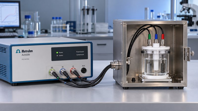
Treat the cell and cabling as part of the measurement system
The potentiostat’s current front end does not operate independently of the cell. Cell capacitance, cable capacitance, and control-loop settings can affect noise, settling, and stability. Voltage noise can be converted into current noise through the connected impedance, so a quiet input test does not necessarily predict performance with an electrochemical cell.
Charging current also creates a range-selection problem. For a capacitor, i = C × dV/dt. As an illustrative calculation, 1 µF subjected to a 0.1 V/s potential ramp produces 100 nA of capacitive current before any faradaic contribution is considered. An experiment targeting picoampere features may therefore require an instrument to handle currents several orders of magnitude larger during other parts of the waveform.
Check how electrochemical analyzers respond to overload and current-range changes. Relevant characteristics include settling time, missing data, switching artifacts, and recovery after saturation. A sensitive range is of limited use if it cannot recover before the required reading. Fixed-range operation can avoid switching artifacts, but only if the range accommodates the waveform without sacrificing necessary sensitivity.
Control-loop stability must also be demonstrated with representative impedance. Ask which stability or bandwidth settings are required and whether those settings compromise the measurement timing. Reference-electrode impedance and counter-electrode compliance should remain within the instrument’s operating limits throughout the experiment.
Leakage and interference can consume the entire signal budget
At picoampere levels, insulation is an active selection concern. From Ohm’s law, 1 V across a 1 TΩ leakage path produces 1 pA. Connector contamination, moisture, damaged insulation, or an unsuitable switching accessory can therefore create an error comparable to the intended signal.
A low-current specification should identify whether it applies at the instrument connector or includes the supplied cable and cell fixture. It should also state relevant temperature, humidity, and voltage conditions. Performance demonstrated with short, clean laboratory connections may not transfer to a longer installation or a humid enclosure.
Shielding and guarding solve different problems. A conductive shield reduces electric-field interference. A driven guard reduces leakage and effective capacitance along supported high-impedance paths by holding a surrounding conductor near the sensitive node’s potential. A guard is not simply another ground, and its connection must follow the instrument’s architecture. Triaxial cabling is valuable where the analyzer actually supports the corresponding guarded arrangement.
Mechanical handling matters as well. Cable motion can generate triboelectric currents, while vibration and changing capacitance can produce disturbances. Low-noise cables should be secured during verification. A Faraday cage can reduce external electric-field pickup, but it will not eliminate internal leakage, ground-loop currents, or real fluctuations in the cell.
Compare instruments in the intended connection configuration, including any computer, stirrer, temperature controller, or other attached equipment. Adding accessories after a successful bench demonstration can introduce new interference paths.
Use staged verification to distinguish instrument limits from cell behavior
A convincing acceptance test separates electronic performance from electrochemical variability. A quiet trace alone is not enough: the system must also reproduce a known signal and respond correctly to changes.
Establish the electronic baseline
Begin with the manufacturer-recommended low-current test configuration. Record the range, bandwidth, filters, warm-up time, cable arrangement, shielding, temperature, and humidity. An open input, shorted input, and resistive load exercise different conditions; none should be treated as a universal representation of an electrochemical cell.
Evaluate baseline mean, RMS variation, drift, and occasional disturbances over a duration relevant to the experiment. Preserve the time series rather than accepting only a cropped screenshot. Long records can reveal thermal drift or periodic interference that a short demonstration misses.
Verify response with a characterized electrical load
A suitable high-value resistor network or low-current source can test gain, polarity, and response at relevant current levels. The test source must have sufficiently low leakage and known uncertainty. At very high resistance, resistor tolerance, voltage dependence, temperature sensitivity, and fixture insulation can limit the reference itself.
Add representative capacitance or an appropriate dummy-cell network to evaluate settling and stability. Apply a waveform that includes the expected transient and observe the return to the low-current region. This is more revealing than testing only a constant current near the center of the most sensitive range.
Confirm performance with the intended chemistry
Use a blank and a representative sample with the actual electrode configuration. Compare baseline stability, repeatability, and the response to a controlled experimental change. If electrical tests pass but the blank remains unstable, electrode condition, contamination, dissolved gases, temperature, or cell construction may be setting the practical limit.
Do not translate an instrument noise figure directly into an analytical detection limit. Detection capability also depends on blank variability, calibration sensitivity, sample preparation, and the measurement protocol.
Make the purchase decision against an agreed operating configuration
Request verification data for the configuration being purchased, not simply the best result available elsewhere in the product family. That includes the current-measurement module, cable set, shielding, software options, and any multiplexer. Switching hardware is particularly important because it can add leakage, capacitance, and settling requirements.
Acceptance limits should reflect the application: maximum baseline variation over a defined interval, acceptable drift, error at selected current points, recovery after a specified transient, and repeatability with a representative cell. Record the settings needed to meet those limits. Otherwise, a supplier may demonstrate low noise using averaging that makes the required experiment impossible.
Software should preserve the evidence behind the result. Confirm access to numerical data, timestamps, range-change records, acquisition settings, and filter information. Automatic smoothing or zero subtraction should be identifiable and controllable. Calibration documentation should cover the relevant ranges and uncertainty; a calibration certificate alone does not establish performance with the intended cell.
The defensible choice is the analyzer that meets the signal, timing, and stability requirements with a reproducible setup. A lower quoted noise floor offers little benefit if achieving it requires unacceptable averaging, frequent manual correction, or a connection arrangement that cannot be maintained. Once the required performance is demonstrated, compare the complete installed cost—including low-current accessories, calibration, and verification effort—rather than paying for sensitivity the experiment cannot use.
Recommended for You
 How to choose electrochemical analyzers for low-current measurementsCompare electrochemical analyzers for precise low-current measurements. Learn how noise, leakage, bandwidth, and real-cell testing help you choose the right instrument.
 What tolerance does a custom gas mixture need for calibration?Choose the right custom gas tolerance for calibration. Learn how blending tolerance, certified uncertainty, and stability affect accuracy—and avoid paying for precision you don’t need.
 How condensation affects stack detector readings in wet flue gasStack detector readings can drift when wet flue gas condenses. Learn how to identify moisture interference, prevent sample losses, and improve emissions monitoring reliability.
 How to prevent condensation in a CO2 analyzer sampling systemPrevent condensation in your CO2 analyzer sampling system. Learn how to control dew point, eliminate cold spots, and manage moisture for reliable readings and fewer costly disruptions.
 How to verify accuracy claims for industrial quality analyzersVerify accuracy claims for industrial quality analyzers with calibration checks, independent testing, and clear acceptance criteria. Learn how to reduce risk and buy with confidence.
 How to calculate cooling loads for an industrial analyzer shelterSize industrial analyzer shelter cooling with confidence. Learn to calculate equipment heat, solar gains, and ventilation loads, then select HVAC capacity for reliable analyzer performance.
 How Much Does a Complete CEMS Integration Project Typically Cost?How much does a complete CEMS integration project typically cost? Explore budget ranges, hidden installation costs, and compliance needs to compare quotes and plan confidently.
 What Is the Typical Response Time for Industrial Air Monitors?What is the typical response time for industrial air monitors? Explore T90, sampling delays, and alarm settings to compare performance and choose the right monitor with confidence.
 Do Regulatory Monitoring Systems Need Third-Party Certification?Do regulatory monitoring systems need third-party certification? Learn when it is required, what certificates prove, and how to verify compliance before buying.
 How Do You Choose Wired or Wireless for Stack Monitoring?Learn how to choose between wired and wireless for stack monitoring. Compare reliability, lifecycle costs, and data recovery to find the right CEMS setup for your site.
 What Happens When Combustible Gas Sensor Calibration Is Overdue?What happens if combustible gas sensor is not recalibrated on time? Discover the risks of inaccurate readings and missed alarms, plus steps to restore reliable protection.
 Can One Multi-Gas Detector Replace Four Separate Analyzers?Find out: can a single multi-gas detector replace four separate analyzers? Compare accuracy, safety, compliance, and lifetime costs to make a confident buying decision.
 Industrial Safety vs. Emission Monitoring: What Are the Differences?What are the main differences between industrial safety and emission monitoring? Compare goals, sensors, response times, and compliance needs to choose the right systems for your facility.
 Is Remote Monitoring Worth the Cost for Small Emission Sources?Is it worth investing in remote monitoring for small emission sources? Compare costs, compliance needs, and potential savings to choose the right solution for your operation.
 How Do You Handle Analyzer Failure During an Environmental Audit?Learn how to handle analyzer failure during environmental compliance audit procedures. Protect evidence, verify data, and restore monitoring with this practical response guide.
 Do VOC Monitors Require Explosion-Proof Certification?Does VOC monitoring require explosion-proof certification? Learn when approval is needed, compare ATEX and IECEx, and choose the right monitor for your site.
 How sample conditioning affects accuracy in petrochemical analyzersImprove accuracy in petrochemical analyzers with smarter sample conditioning. Discover how phase control, filtration, and transport design prevent bias and deliver reliable process data.
 How to troubleshoot sensor drift in industrial gas detectorsIndustrial gas detectors showing sensor drift? Learn how to verify calibration gas, identify root causes, and determine when sensor replacement is needed for reliable monitoring.
 How to judge whether a competitive price reflects real valueCompetitive Price: learn how to compare scope, compliance, performance, and lifecycle costs to identify real value, reduce risk, and make smarter purchasing decisions.
 When custom gas analysis is the right fit for complex process streamsCustom gas analysis for complex process streams: learn when tailored sampling, interference control, and reliable measurement design deliver confident decisions.
 When does a laser gas analyzer meet stack emissions monitoring needs?Laser gas analyzer for stack emissions: learn when it delivers fast, reliable data, how to assess installation risks, and what to verify for CEMS compliance.
 How to select a hazardous gas analyzer for confined spacesHazardous gas analyzer selection for confined spaces: compare sensors, sampling, certifications, alarms, and maintenance to protect workers and choose with confidence.
 When is a single gas analyzer sufficient for workplace safety monitoring?Discover when a single gas analyzer delivers reliable workplace safety monitoring, and learn the key limits, calibration needs, and risks that require broader detection.
 How to choose an ambient gas analyzer for low-level leak detectionAmbient gas analyzer selection for low-level leak detection: compare sensitivity, cross-sensitivity, sampling design, alarms, and calibration for reliable site performance.
 How to tell when an oxygen sensor needs replacementOxygen sensor replacement signs explained: learn how live data, fault codes, wiring checks, and exhaust inspections pinpoint the real issue before you buy.
 How laser gas analyzers improve combustion control in steel furnacesLaser gas analyzer for steel industry applications delivers fast in-situ O₂ and CO data to optimize furnace combustion, cut fuel waste, and improve steel heating stability.
 How to verify whether explosion proof equipment meets site requirementsExplosion proof equipment verification made practical: match zones, gas or dust groups, temperature classes, certificates, and installation conditions for confident compliance.
 How industrial gas analysis helps detect contamination before releaseIndustrial Gas Analysis helps detect moisture, oil, oxygen, and toxic contaminants before release—protecting processes, ensuring compliance, and reducing costly risks.
 When is electrochemistry detection the right choice for water analysis?Electrochemistry detection for water analysis: learn when fast, reliable monitoring of ions, chlorine, pH, and more delivers actionable results.
 How industrial standards reduce quality risks in supplier selectionIndustrial Standard guidance helps quality and safety managers reduce supplier risks, verify compliance, strengthen traceability, and build resilient instrumentation supply chains.
 When does a multi-component system reduce installation complexity?Multi component systems reduce installation complexity when they eliminate field interfaces, streamline commissioning, and provide proven compatibility. Learn how to assess total cost and supplier accountability.
 How to size an industrial control shelter for outdoor equipmentIndustrial control shelter sizing guide: optimize layout, HVAC, access, safety, and expansion space for reliable outdoor equipment operations.




Search Categories
Search Categories
- Smart Meters & Power Quality
- Transformer Gas Analyzers
- BESS Thermal Runaway Detectors
- Energy, Power & Smart Grid Monitoring
- Optical Profilers & CMM
- Ultrasonic & X-Ray NDT
- Calibration Standards
- Precision Metrology & NDT
- Water Quality Analyzers
- CEMS & VOCs Monitors
- Price Trends
- Import & Export Updates
- Market Trends
- Industry News
- Industry Insights
Latest Article
- How to choose electrochemical analyzers for low-current measurementsCompare electrochemical analyzers for precise low-current measurements. Learn how noise, leakage, bandwidth, and real-cell testing help you choose the right instrument.Posted by:
- What tolerance does a custom gas mixture need for calibration?Choose the right custom gas tolerance for calibration. Learn how blending tolerance, certified uncertainty, and stability affect accuracy—and avoid paying for precision you don’t need.Posted by:
- How condensation affects stack detector readings in wet flue gasStack detector readings can drift when wet flue gas condenses. Learn how to identify moisture interference, prevent sample losses, and improve emissions monitoring reliability.Posted by:
Please give us a message