How does a CO analyzer control parking garage ventilation?


A CO analyzer for parking garage ventilation measures carbon monoxide in garage air and sends a concentration or alarm signal to a controller. The controller compares that signal with configured thresholds and starts, stops, or adjusts exhaust fans to remove contaminated air and draw in replacement air.
The measurement alone does not guarantee safe ventilation. Performance depends on where sensors are placed, how quickly the control sequence responds, whether airflow reaches the affected area, and what happens when a sensor, communication link, or fan fails.
How a CO analyzer for parking garage ventilation closes the control loop
A garage system combines gas detection with mechanical equipment and a control strategy. The analyzer may be a standalone device with built-in relays, a network of detectors connected to a dedicated controller, or a sensor integrated into a building automation system (BAS). Regardless of architecture, the control path has the same essential elements:
- Sample: Ambient air reaches a sensor positioned in a representative part of the garage.
- Measure: The sensor converts its response to CO into a concentration, commonly displayed in parts per million (ppm).
- Decide: A controller compares the reading, or a time-averaged value, with programmed conditions.
- Act: A relay, variable-frequency drive (VFD), or BAS command operates the exhaust and associated make-up air equipment.
- Verify: The system continues monitoring as concentration changes; fan-status and airflow feedback can confirm whether the commanded response occurred.
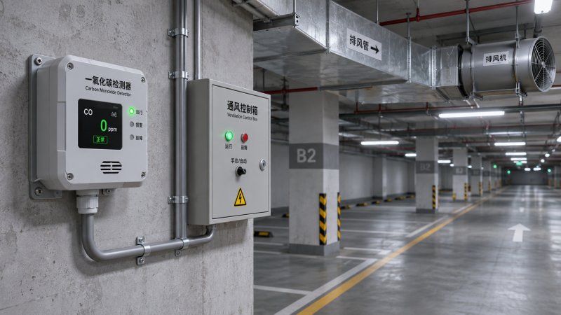
The loop is only as reliable as its weakest connection. A detector can report an accurate value while a failed fan belt, closed damper, or poor sensor location prevents that value from producing the intended improvement in air quality.
From gas concentration to an electrical signal
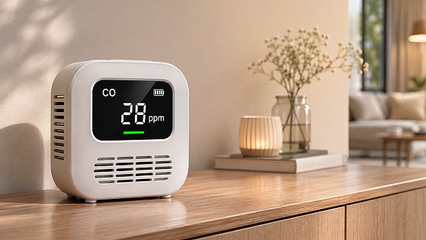
Many fixed garage detectors use an electrochemical CO sensor. CO diffuses through an opening to an electrochemical cell, where a reaction produces a small electrical current related to concentration. The instrument conditions that signal, applies calibration, and reports a reading or changes a relay state.
Other sensing technologies exist, but the measurement principle alone is not enough to establish suitability. Evaluate the specified measurement range, accuracy, resolution, response time, environmental limits, cross-sensitivity, expected sensor life, and maintenance requirements for the actual garage conditions.
Temperature and humidity affect sensor behavior, while condensation, dust, cleaning chemicals, and other gases can impair measurement or cause interference. Manufacturer specifications should identify operating limits and known cross-sensitivities; they should also distinguish normal operating conditions from short-term storage or survival limits.
Signal choices and their consequences
For example, a 4–20 mA input is meaningful only if both ends use the same ppm scaling. An incorrect range configuration can cause the controller to understate concentration even when the detector itself is functioning correctly.
Control sequences: switching, staging, and modulation
The simplest sequence starts a fan when CO exceeds an on-threshold and stops it after the concentration falls below a lower off-threshold. The separation between those points is hysteresis; it helps prevent repeated starts when a reading fluctuates around one value.
Staged systems can bring on additional fans or fan speeds as concentration increases. A modulating system can use a VFD to vary speed according to concentration or another defined control function. Modulation can avoid unnecessary full-speed operation, but only if the fan, ductwork, make-up air path, and control sequence remain effective at the commanded speed.
Consider a hypothetical zone where vehicles enter in a short burst. CO rises, the detector calls for ventilation, and the exhaust fan starts. After the vehicles leave, the fan continues until the measured concentration falls below the release condition and any required minimum run time expires. The delay between emission, detection, fan response, and dilution means that fan start does not instantly restore the entire zone to the sensor reading.
Control logic needs explicit rules for:
- Minimum run and off times: Reduce excessive cycling without delaying a necessary response.
- Sensor aggregation: Define whether the highest reading, a local zone reading, or another method controls each fan. Averaging several sensors can conceal a localized high concentration.
- Minimum ventilation: Maintain any baseline airflow required by the applicable design or code, even when CO is low.
- Overrides and priorities: Coordinate occupancy schedules, manual commands, fire or smoke-control modes, and other safety functions under the approved sequence.
- Feedback: Identify whether the fan is merely commanded on or is actually running and producing the intended airflow.
Energy savings come from avoiding airflow that is not required under the approved operating conditions, not from substituting a gas reading for an engineered ventilation design. Fan capacity, air distribution, and make-up air must still support the required response.
Setpoints, exposure limits, and code requirements
A ventilation start point, a high-level alarm, and an occupational exposure limit serve different purposes. They should not be treated as interchangeable numbers. A fan-control threshold is part of a mechanical sequence; an alarm threshold triggers a defined warning or protective action; an exposure limit generally has a specified averaging period and applies under a particular regulatory framework.
Setpoints and delays should be established from the adopted local building and mechanical codes, the approved design, relevant workplace requirements, and the equipment documentation. Code editions and local amendments matter. A value used in one jurisdiction or application is not automatically acceptable in another.
When reviewing a proposed sequence, ask whether the threshold is an instantaneous reading, a filtered value, or a time-weighted average. Also confirm the sensor response time, any intentional delay before fan activation, the alarm reset conditions, and the action required if concentration remains high despite ventilation. Long averaging or delay periods can suppress nuisance responses, but they can also postpone action during a rapid rise.
Sensor placement determines what the controller can see
CO mixes with air, but a garage does not necessarily have uniform concentrations. Vehicle queues, ramps, enclosed corners, columns, supply-air jets, exhaust inlets, and traffic patterns create local differences. A detector placed directly in a clean-air stream can report a low value while another part of the zone remains contaminated.
The layout should reflect the approved coverage design and the detector manufacturer’s installation instructions, including mounting height, spacing, and restrictions near obstructions or airflow openings. Avoid assuming that a sensor’s advertised coverage area applies unchanged to every geometry; walls, partitions, and separate levels can limit how representative a reading is.
Each control zone should have a clear relationship between the sensors observing it and the fans serving it. If one sensor calls a remote fan that does not effectively ventilate the affected space, the control sequence is incomplete even though the electrical connection works.
CO is also not the only contaminant relevant to vehicle exhaust. Where the applicable design or code requires nitrogen dioxide or other detection, a CO-only system does not replace those functions. The sensor network and ventilation logic must address the pollutants specified for the facility.
Failure behavior and commissioning evidence
Loss of a detector signal must not be silently interpreted as clean air. The design should define the response to sensor fault, expired sensor life, power loss, open wiring, invalid analog input, and communication timeout. Depending on the approved safety and mechanical strategy, the response can include a fault alarm and operation at a designated ventilation state.
A commanded fan response is not proof of ventilation. Motor overloads, VFD faults, failed belts, closed dampers, blocked air paths, and insufficient make-up air can all prevent the expected airflow. Status contacts, airflow proving, and fault notifications should be selected and tested against the system’s risk assessment and design requirements.
Commissioning should demonstrate the complete chain rather than only checking the detector display. A practical acceptance record should cover:
- Sensor locations and identification against the approved drawings, including zone-to-fan assignments.
- Configuration of measurement ranges, setpoints, hysteresis, timers, and communication points.
- Detector response using an approved test method and suitable test gas, following the manufacturer’s instructions.
- Fan, VFD, damper, and make-up air response at each relevant control stage, with airflow verification as required by the design.
- Alarm annunciation and the documented response to sensor, power, wiring, and communication faults.
- Return to normal operation, including reset behavior and any minimum run time.
A bump test checks that a detector responds to gas and that associated actions occur; it does not by itself establish measurement accuracy across the range. Calibration or calibration verification, sensor replacement, and functional testing should follow the manufacturer’s instructions and applicable facility requirements, with records retained for comparison over time.
What distinguishes a dependable system?
A dependable installation links representative measurement, a documented control sequence, verified airflow, and a defined fault response. Concentration readings should be traceable to the correct zone, and every threshold should have a clear purpose rather than being copied from an unrelated exposure limit or project.
The decisive evidence is an end-to-end test: introduce a controlled demand, observe the correct ventilation response, confirm the alarm and fault paths, and verify that the system returns to its intended state. That evidence is more useful than a sensor specification or fan command considered in isolation.
Recommended for You
 How does a CO analyzer control parking garage ventilation?Discover how a CO analyzer for parking garage ventilation controls fans, supports efficient airflow, and helps maintain a safer garage environment.
 How to choose a gas quality analyzer for natural gas pipelinesChoose the right gas quality analyzer for natural gas pipelines. Compare technologies, sampling systems and performance to support reliable decisions.
 How does pressure affect laser oxygen analyzer readings?Laser oxygen analyzer readings can shift with pressure. Learn how compensation, sample conditions and calibration affect accuracy—and how to troubleshoot changes.
 How to identify regulatory compliance requirements for your businessRegulatory Compliance starts with knowing which rules apply. Learn how to assess obligations, document decisions, and build effective controls for your business.
 How to choose industrial air monitors for workplace VOCsChoose industrial air monitors for workplace VOCs with confidence. Compare sensor technologies, placement, calibration, and safety requirements.
 Laser vs infrared gas analyzers for stack monitoring: Which handles water vapor interference better?Laser vs infrared gas analyzer stack monitoring: Discover which technology better handles water vapor interference and how to choose for your application.
 Can an air detector identify carbon monoxide indoors?Can an air detector identify carbon monoxide indoors? Learn which sensors detect CO, how to check device specifications, and why a certified alarm matters.
 How does a paramagnetic gas analyzer measure oxygen?Discover how a paramagnetic gas analyzer measures oxygen, what affects accuracy, and how to choose the right solution for your application.
 How to choose a reliable gas analyzer for low concentrationsChoose a reliable gas analyzer for low concentrations. Compare technologies, sampling, calibration and supplier evidence to make a confident purchase.
 How does cross-sensitivity affect multi gas analysis accuracy?Discover how cross-sensitivity affects multi gas analysis accuracy, and learn how to identify interference, validate compensation, and improve measurement reliability.
 How to choose metrics for sustainable monitoringSustainable Monitoring starts with metrics that drive action. Learn how to define boundaries, assess data quality, and track meaningful improvements.
 How to verify a trusted manufacturer's production capacityTrusted Manufacturer capacity claims need proof. Learn how to verify production plans, bottlenecks, quality records and supply risks before you place an order.
 How to choose an emission controller for an industrial boilerChoose the right emission controller for your industrial boiler. Compare technologies, operating conditions, compliance needs, and costs.
 How to choose composition analyzers for low-concentration measurementsChoose composition analyzers with confidence. Discover how quantification limits, sample handling and matrix effects shape reliable low-concentration measurements.
 How does online analysis compare with laboratory testing for water quality monitoring?Online analysis vs. laboratory testing: compare speed, accuracy, costs, and compliance to find the right water quality monitoring strategy.
 How to choose the right detection range for a custom gas analyzerChoose the right custom gas analyzer detection range with practical guidance on accuracy, exposure limits, calibration, and supplier evaluation.
 How does multi component monitoring detect gases in stack emissions?Discover how multi component monitoring detects stack gases, manages interference and supports reliable emissions reporting. Explore key CEMS selection factors.
 How bright should an industrial monitor be for outdoor use?Choosing an outdoor industrial monitor? Learn why 1,000 nits is a starting point and how glare, contrast, and heat affect sunlight readability.
 How does water vapor affect infrared gas analyzers?Infrared gas analyzers can be affected by humidity, condensation and spectral interference. Learn how to protect sample integrity and achieve reliable results.
 How to reduce customer support response timesReduce Customer Support response times with actionable tips for reporting equipment faults, choosing the right channel, and getting expert help faster.
 How to choose a low range analyzer for trace-level measurementsChoose the right low range analyzer for trace-level measurements. Compare detection limits, sampling, calibration and support to make a confident decision.
 How to choose combustible gas detectors for a specific gasChoose combustible gas detectors with confidence. Compare sensor technologies, gas response, calibration, placement, and certification for your application.
 How to choose an air quality analyzer for the pollutants you need to measureChoose an air quality analyzer with confidence. Compare pollutant measurement methods, sampling, accuracy and calibration to find the right fit for your needs.
 How to choose industrial metrology tools for tight tolerancesChoose industrial metrology tools for tight tolerances with confidence. Compare uncertainty, calibration, tool types, and costs to reduce inspection risk.
 How moisture affects fixed analyzer accuracy in stack gas monitoringImprove fixed analyzer accuracy in stack gas monitoring. Discover how moisture causes dilution, interference, and sample loss—and learn practical ways to protect emissions data.
 How does production line speed affect in-line measurement accuracy?Discover how production line speed affects in-line measurement accuracy. Explore sensor response, sampling, and timing to boost throughput without compromising quality.
 How condensation affects HCl concentration analyzer accuracyHCl concentration analyzer accuracy can suffer when condensation traps HCl. Learn how to spot sampling losses, prevent low readings, and improve measurement reliability.
 How does cross-interference affect multi-component gas analyzers?How does cross-interference affect multi component gas analyzers? Explore measurement errors, compensation limits, and validation tips to choose the right system for your process.
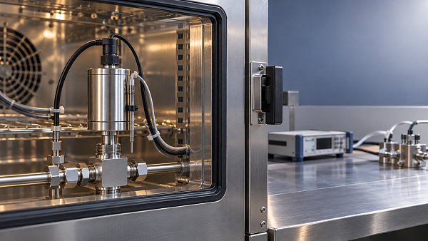
 How does temperature affect high-accuracy sensor performance?Explore how temperature affects high accuracy sensor performance. Learn to reduce thermal drift, evaluate compensation, and select the right sensor for reliable measurements.
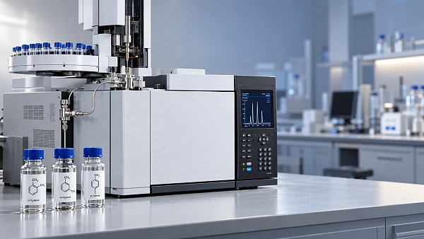
 Can a C4H8O concentration analyzer distinguish between isomers?Can a C4H8O concentration analyzer distinguish isomers? Compare GC, FTIR and MS methods, uncover selectivity limits, and learn what to validate before choosing your instrument.
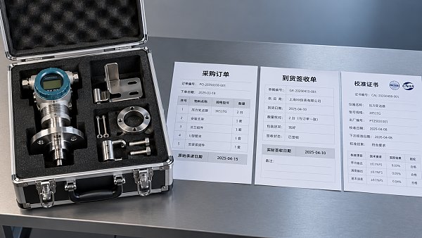
 How to identify a reliable supplier using on-time delivery recordsIdentify a Reliable Supplier by verifying on-time delivery records, original commitments, and complete shipments. Learn practical checks to reduce purchasing risk and protect your project schedule.
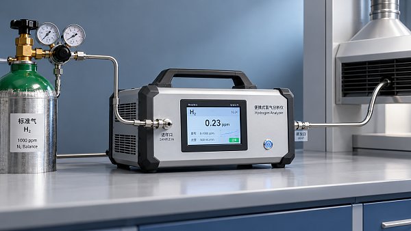
 How sensitive should a portable hydrogen analyzer be for lab use?Choose a portable hydrogen analyzer for laboratory use with the right quantification limit, accuracy, and range. Learn how to verify performance and avoid costly buying mistakes.

Search Categories
Search Categories
- Smart Meters & Power Quality
- Transformer Gas Analyzers
- BESS Thermal Runaway Detectors
- Energy, Power & Smart Grid Monitoring
- Optical Profilers & CMM
- Ultrasonic & X-Ray NDT
- Calibration Standards
- Precision Metrology & NDT
- Water Quality Analyzers
- CEMS & VOCs Monitors
- Price Trends
- Import & Export Updates
- Market Trends
- Industry News
- Industry Insights
Latest Article
- How does a CO analyzer control parking garage ventilation?Discover how a CO analyzer for parking garage ventilation controls fans, supports efficient airflow, and helps maintain a safer garage environment.Posted by:
- How to choose a gas quality analyzer for natural gas pipelinesChoose the right gas quality analyzer for natural gas pipelines. Compare technologies, sampling systems and performance to support reliable decisions.Posted by:
- How does pressure affect laser oxygen analyzer readings?Laser oxygen analyzer readings can shift with pressure. Learn how compensation, sample conditions and calibration affect accuracy—and how to troubleshoot changes.Posted by:
Please give us a message