Unstable CH4 Readings in Biogas Monitoring? Check Moisture and Sample Flow


Unstable methane readings often start in the sampling system. Before changing calibration settings on a CH4 analyzer for biogas monitoring, establish whether the gas reaching the measurement cell is consistently dry enough, flowing within specification, and arriving at an acceptable pressure. Condensation, a wet filter, or intermittent pump delivery can produce fluctuations that resemble sensor drift.
Record the methane trend alongside sample flow, available pressure readings, and cooler status before disturbing the installation. Note whether instability follows cold mornings, drain cycles, filter changes, or switching between sampling points. These relationships help separate a delivery problem from a change in biogas composition.
Read the fluctuation pattern before opening the sample line
A slowly falling methane value, sharp downward spikes, and a delayed response to process changes deserve different investigations. The pattern alone does not establish the cause, but it identifies the most useful next measurement.
Keep the original settings during this investigation. Recalibrating against a sample with changing moisture content or pressure can hide the fault temporarily and introduce an offset once the sampling problem is repaired.
Follow the moisture path from the probe to the cell
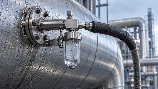
Biogas commonly leaves the process with substantial water vapor. Condensation begins wherever the gas temperature drops below its dew point at the local pressure. A warm cabinet does not prevent water formation in an exposed tube, a metal bulkhead fitting, or a low point upstream.
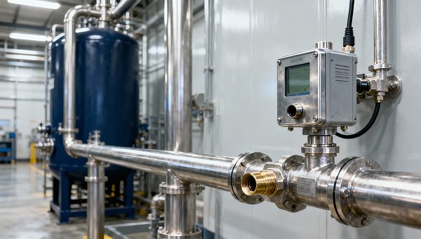
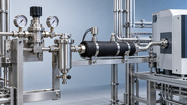
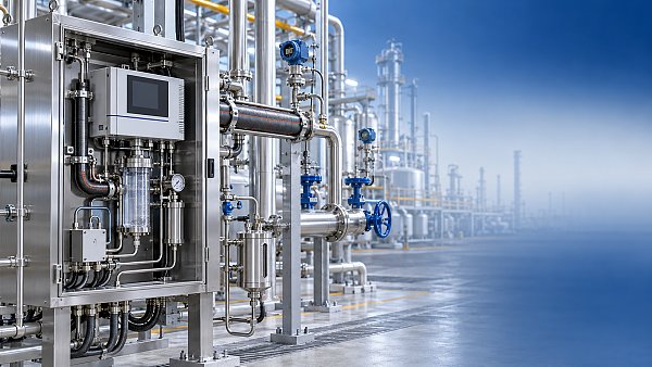
Trace the installed route: extraction probe, transfer tubing, separator or cooler, drain, filters, pump, analyzer inlet, and discharge. The order varies between systems. Identify where liquid should be removed and where downstream components require protection from it.
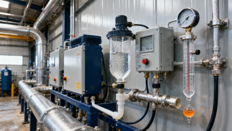
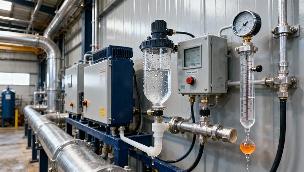
Inspect accessible transparent bowls and tubing for droplets, pooling, or liquid movement during pump operation. A clear separator bowl does not prove that the downstream sample is dry. Fine droplets can pass through an ineffective separator, and vapor can condense later if the outlet gas meets a colder surface.
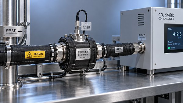
Low points are especially troublesome because they store condensate and release it intermittently. This produces unstable delivery even when the moisture load at the extraction point remains fairly constant. Restore the intended drainage slope and remove unintended tubing loops. Where heating is specified, verify temperature along the route, including fittings and cabinet entry points, rather than relying only on the controller display.
Before opening the system, isolate and depressurize the relevant section using the site procedure. Biogas can contain flammable methane and toxic hydrogen sulfide. Route discharged gas to the designated safe outlet, and handle condensate under the site's procedure for potentially contaminated liquids.
A running cooler does not prove effective drying
Compare the cooler's actual operating temperature with its specified range, then inspect drainage. A blocked drain allows liquid to accumulate; a leaking automatic drain can admit air into a suction system or disturb sample pressure during each cycle. Correlating those cycles with the methane trend is often more informative than a single temperature reading.
A cooler also needs to handle the installed gas flow, inlet temperature, and moisture load. Increasing flow beyond its design conditions reduces residence time and raises the cooling duty. If instability began after a pump adjustment or a sampling-system modification, confirm that the conditioning equipment still operates within its rating.
Inspect downstream filters for wetting, discoloration, and increased pressure drop. A particulate filter is not automatically a water separator. Hydrophobic membranes have specified limits and require correct orientation and drainage arrangements. Replacing a wet element without correcting the source of liquid usually leads to another restriction.
Dryer substitutions need similar care. An adsorbent, membrane dryer, or alternative conditioning arrangement can affect sample composition or pressure. Use a method validated for the measured gases and the analyzer configuration; adding an unspecified drying material creates another variable in the measurement.
Separate moisture interference from a change in reporting basis
Water affects methane measurement through more than one mechanism. Liquid contamination can foul an optical path or obstruct gas movement. Water vapor can also influence the measurement through spectral interference or compensation limits, depending on the sensing method. Confirm the permitted humidity and noncondensing conditions in the instrument documentation.
Removing water also changes the concentration basis. Methane expressed as a fraction of wet gas differs from methane expressed as a fraction of dry gas, even when the methane-to-dry-gas ratio remains unchanged. A change in drying performance can therefore shift the displayed concentration without any sensor fault.
For concentrations expressed on consistent molar or volume-fraction bases, the relationship is dry-basis CH4 = wet-basis CH4 / (1 − water-vapor fraction). This relationship describes dilution by water; it does not correct liquid contamination, optical interference, or pressure errors. Apply it only when water content is known and the instrument's existing correction is understood.
When comparing an online reading with another analyzer or a laboratory result, establish whether both values use the same moisture basis and sampling conditions. Otherwise, an apparent calibration disagreement can arise from sample preparation alone.
Measure the flow that actually passes through the analyzer
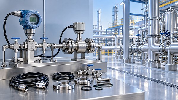
A pump running normally is not evidence of correct sample flow. Neither is a flowmeter installed only on a bypass. In systems with a fast transport loop and a smaller measurement branch, substantial bypass flow can coexist with inadequate flow through the cell.
Locate the manufacturer's specified flow measurement point and distinguish actual volumetric flow from flow reported at reference conditions. Compare the reading with the permitted range under the required pressure conditions. A variable-area flowmeter calibrated for a particular gas and pressure needs the applicable correction or interpretation for the installed service.
Use a compatible measurement device and a connection method that preserves the intended flow path. Adding a restrictive meter at the outlet can change cell pressure and create the symptom being investigated. Where the analyzer reports internal flow or pressure, compare those values with an independent measurement only through approved connections.
Low flow increases transport delay and slows sample replacement inside the instrument. Excessive flow can exceed conditioning capacity or alter cell pressure. Increasing pump speed until the display appears responsive is therefore a poor substitute for restoring the specified operating conditions.
Pressure deserves separate attention. Infrared methane measurements respond to gas density, and pressure compensation has an operating range. A restricted exhaust, submerged vent outlet, or shared discharge header can create backpressure even when the inlet flow appears acceptable. Inspect the complete discharge route.
Distinguish a restriction from a weakening pump
Compare pressures around accessible parts of the sampling path. An increasing pressure drop across a filter points toward restriction there. Reduced delivery without a corresponding restriction directs attention toward pump valves, diaphragm condition, drive operation, or leakage. Interpret the readings according to whether the pump draws through or pushes through the analyzer.
Suction-side leaks require particular care. They can dilute methane with ambient air without releasing obvious gas externally. Loose compression fittings, damaged seals, and drain connections are plausible entry points. Use the approved leak-testing method; tightening every fitting indiscriminately can damage tubing and create additional leaks.
Pulsation requires more than an average reading. A float that repeatedly rises and falls, or a pressure trace synchronized with the pump, indicates uneven delivery. Assess pump condition and any specified pulsation damping arrangement. Do not install an improvised reservoir: added volume increases delay and creates another location for condensate accumulation.
Use controlled gas comparisons to locate the fault
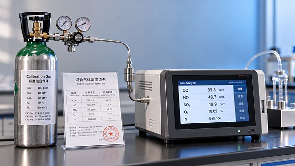
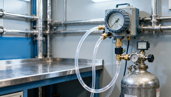
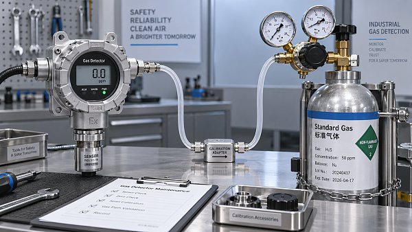
Once visible moisture problems and obvious restrictions have been addressed, use a suitable certified reference gas to test stability without immediately adjusting calibration. Match the gas, regulator, flow, and pressure to the manufacturer's procedure. Allow the specified warm-up and settling time before interpreting the result.
A useful isolation sequence is:
- Introduce reference gas at the designated analyzer test inlet. Stable readings support correct operation under those test conditions. Continued instability directs attention toward the instrument, its local gas connections, pressure control, or reference-gas delivery.
- If the sampling system has an approved upstream test connection, introduce the same gas there under permitted conditions. Instability that appears only through this longer route points toward the intervening tubing, conditioning equipment, pump, or valves.
- Return to process gas and compare methane, flow, pressure, and drainage behavior together. A dry reference gas does not reproduce the moisture load or all matrix effects of biogas, so stability on reference gas alone does not validate the complete process measurement.
Avoid forcing reference gas into a suction system at excessive pressure. This can mask leaks, alter pump behavior, or exceed the analyzer's inlet limit. Use the specified demand regulator or test arrangement where required.
Change one variable at a time. Replacing a filter, adjusting pump speed, draining the cooler, and recalibrating together removes the evidence needed to identify the original cause. Record each intervention and its effect on both delivery conditions and methane stability.
Confirm recovery after the sample has fully refreshed
Immediately after maintenance, the displayed value can still represent gas held in tubing, filters, and the measurement cell. Transport delay increases with internal volume and decreases with flow. Dividing line volume by actual line flow provides a rough transit estimate, but mixing, conditioning volumes, and instrument response extend the time needed for a settled reading.
Evaluate recovery over the operating conditions that previously triggered the fault. A stable trace immediately after draining a separator does not establish that automatic drainage works. Similarly, a warm daytime test leaves a suspected cold-weather condensation problem unresolved. Observe the relevant drain cycles, sampling-point changes, or temperature conditions.
Document the restored flow and pressure, conditioning status, replaced parts, and reference-gas response. Adjust calibration only if a repeatable error remains under valid test conditions. If instability persists with compliant sample delivery and stable reference-gas supply, the recorded evidence provides a focused basis for investigating the measurement cell, internal pressure sensing, electronics, or manufacturer-specific diagnostics.
Recommended for You
 How sensitive should a portable hydrogen analyzer be for lab use?Choose a portable hydrogen analyzer for laboratory use with the right quantification limit, accuracy, and range. Learn how to verify performance and avoid costly buying mistakes.
 How to set industrial calibration intervals based on equipment riskSet industrial calibration intervals based on equipment risk, drift, and as-found data. Learn when to shorten or extend schedules to improve reliability and avoid unnecessary costs.
 How to choose electrochemical analyzers for low-current measurementsCompare electrochemical analyzers for precise low-current measurements. Learn how noise, leakage, bandwidth, and real-cell testing help you choose the right instrument.
 What tolerance does a custom gas mixture need for calibration?Choose the right custom gas tolerance for calibration. Learn how blending tolerance, certified uncertainty, and stability affect accuracy—and avoid paying for precision you don’t need.
 How condensation affects stack detector readings in wet flue gasStack detector readings can drift when wet flue gas condenses. Learn how to identify moisture interference, prevent sample losses, and improve emissions monitoring reliability.
 How to prevent condensation in a CO2 analyzer sampling systemPrevent condensation in your CO2 analyzer sampling system. Learn how to control dew point, eliminate cold spots, and manage moisture for reliable readings and fewer costly disruptions.
 How to verify accuracy claims for industrial quality analyzersVerify accuracy claims for industrial quality analyzers with calibration checks, independent testing, and clear acceptance criteria. Learn how to reduce risk and buy with confidence.
 How to calculate cooling loads for an industrial analyzer shelterSize industrial analyzer shelter cooling with confidence. Learn to calculate equipment heat, solar gains, and ventilation loads, then select HVAC capacity for reliable analyzer performance.
 Unstable CH4 Readings in Biogas Monitoring? Check Moisture and Sample FlowCH4 analyzer for biogas monitoring giving unstable readings? Discover how moisture, sample flow, and pressure checks help pinpoint faults and restore reliable methane measurements.
 Buying a CO2 Analyzer for Brewery Gas Recovery: Costs Beyond the Purchase PriceBuying a CO2 analyzer for brewery applications? Compare sampling, installation, calibration, and downtime costs to uncover hidden expenses and make a smarter gas recovery investment.
 Where to Place CO Analyzers for Effective Parking Garage VentilationOptimize your CO analyzer for parking garage ventilation with practical placement tips. Learn how sensor height, airflow, and zone coverage support timely detection and effective fan control.
 NDIR vs. FTIR Gas Analyzers: Which Fits Your Environmental Research?Find the right infrared gas analyzer for environmental research. Compare NDIR vs. FTIR on sensitivity, gas coverage, sampling needs, and cost to choose confidently for your study.
 Oxygen Analyzers for Diving: Calibration Checks Before Nitrox BlendingUsing an oxygen analyzer for diving applications? Discover essential calibration, sensor, and sampling checks before nitrox blending to support reliable readings.
 How Paramagnetic Oxygen Analyzers Work and Why Sample Pressure MattersLearn how a paramagnetic oxygen analyzer works, why sample pressure affects accuracy, and what to check in compensation and calibration before choosing your system.
 How Much Does a Complete CEMS Integration Project Typically Cost?How much does a complete CEMS integration project typically cost? Explore budget ranges, hidden installation costs, and compliance needs to compare quotes and plan confidently.
 What Is the Typical Response Time for Industrial Air Monitors?What is the typical response time for industrial air monitors? Explore T90, sampling delays, and alarm settings to compare performance and choose the right monitor with confidence.
 Do Regulatory Monitoring Systems Need Third-Party Certification?Do regulatory monitoring systems need third-party certification? Learn when it is required, what certificates prove, and how to verify compliance before buying.
 How Do You Choose Wired or Wireless for Stack Monitoring?Learn how to choose between wired and wireless for stack monitoring. Compare reliability, lifecycle costs, and data recovery to find the right CEMS setup for your site.
 What Happens When Combustible Gas Sensor Calibration Is Overdue?What happens if combustible gas sensor is not recalibrated on time? Discover the risks of inaccurate readings and missed alarms, plus steps to restore reliable protection.
 Can One Multi-Gas Detector Replace Four Separate Analyzers?Find out: can a single multi-gas detector replace four separate analyzers? Compare accuracy, safety, compliance, and lifetime costs to make a confident buying decision.
 Industrial Safety vs. Emission Monitoring: What Are the Differences?What are the main differences between industrial safety and emission monitoring? Compare goals, sensors, response times, and compliance needs to choose the right systems for your facility.
 Is Remote Monitoring Worth the Cost for Small Emission Sources?Is it worth investing in remote monitoring for small emission sources? Compare costs, compliance needs, and potential savings to choose the right solution for your operation.
 How Do You Handle Analyzer Failure During an Environmental Audit?Learn how to handle analyzer failure during environmental compliance audit procedures. Protect evidence, verify data, and restore monitoring with this practical response guide.
 Do VOC Monitors Require Explosion-Proof Certification?Does VOC monitoring require explosion-proof certification? Learn when approval is needed, compare ATEX and IECEx, and choose the right monitor for your site.
 How sample conditioning affects accuracy in petrochemical analyzersImprove accuracy in petrochemical analyzers with smarter sample conditioning. Discover how phase control, filtration, and transport design prevent bias and deliver reliable process data.
 How to troubleshoot sensor drift in industrial gas detectorsIndustrial gas detectors showing sensor drift? Learn how to verify calibration gas, identify root causes, and determine when sensor replacement is needed for reliable monitoring.
 How to judge whether a competitive price reflects real valueCompetitive Price: learn how to compare scope, compliance, performance, and lifecycle costs to identify real value, reduce risk, and make smarter purchasing decisions.
 When custom gas analysis is the right fit for complex process streamsCustom gas analysis for complex process streams: learn when tailored sampling, interference control, and reliable measurement design deliver confident decisions.
 When does a laser gas analyzer meet stack emissions monitoring needs?Laser gas analyzer for stack emissions: learn when it delivers fast, reliable data, how to assess installation risks, and what to verify for CEMS compliance.
 How to select a hazardous gas analyzer for confined spacesHazardous gas analyzer selection for confined spaces: compare sensors, sampling, certifications, alarms, and maintenance to protect workers and choose with confidence.
 When is a single gas analyzer sufficient for workplace safety monitoring?Discover when a single gas analyzer delivers reliable workplace safety monitoring, and learn the key limits, calibration needs, and risks that require broader detection.
 How to choose an ambient gas analyzer for low-level leak detectionAmbient gas analyzer selection for low-level leak detection: compare sensitivity, cross-sensitivity, sampling design, alarms, and calibration for reliable site performance.
Search Categories
Search Categories
- Smart Meters & Power Quality
- Transformer Gas Analyzers
- BESS Thermal Runaway Detectors
- Energy, Power & Smart Grid Monitoring
- Optical Profilers & CMM
- Ultrasonic & X-Ray NDT
- Calibration Standards
- Precision Metrology & NDT
- Water Quality Analyzers
- CEMS & VOCs Monitors
- Price Trends
- Import & Export Updates
- Market Trends
- Industry News
- Industry Insights
Latest Article
- How sensitive should a portable hydrogen analyzer be for lab use?Choose a portable hydrogen analyzer for laboratory use with the right quantification limit, accuracy, and range. Learn how to verify performance and avoid costly buying mistakes.Posted by:
- How to set industrial calibration intervals based on equipment riskSet industrial calibration intervals based on equipment risk, drift, and as-found data. Learn when to shorten or extend schedules to improve reliability and avoid unnecessary costs.Posted by:
- How to choose electrochemical analyzers for low-current measurementsCompare electrochemical analyzers for precise low-current measurements. Learn how noise, leakage, bandwidth, and real-cell testing help you choose the right instrument.Posted by:
Please give us a message