
How to choose a process sensor for high-temperature applications


When a process runs hot, the sensor is often asked to do more than measure temperature. It may be exposed to pressure cycling, corrosive vapors, thermal shock, vibration, washdown, electrical noise, and long periods of limited access. A process sensor that performs well on a test bench can become the weak link once it is installed on a cracking furnace, thermal oil loop, kiln, autoclave, steam header, gas turbine auxiliary system, or high-temperature reactor.
For technical evaluators, choosing a process sensor for high-temperature service is therefore not a simple exercise in finding the highest temperature rating on a datasheet. The better question is: Can this sensing assembly deliver trustworthy process data throughout its expected operating life, under the real conditions of this installation?
That distinction matters. In automated process control, a drifting or slow sensor can lead to poor product quality, unnecessary energy consumption, unplanned shutdowns, or safety margins that look acceptable only because the measurement itself is no longer reliable.
Start with the actual thermal profile, not the maximum temperature
Many procurement specifications state a single maximum operating temperature. That number is necessary, but it rarely tells the whole story. A high-temperature application should be defined by its complete thermal profile: normal operating temperature, maximum excursion, startup and shutdown ramp rate, upset conditions, exposure duration, and temperature distribution around the installation point.
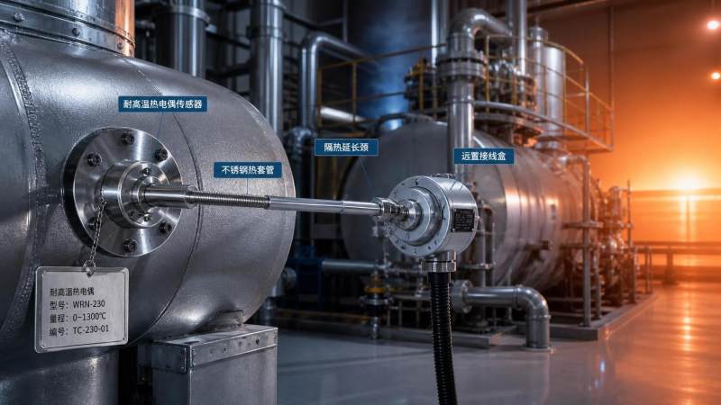
Consider a sensor mounted through a reactor wall. The process-facing tip may see 550°C, while the connection head sits in a much cooler ambient zone. In another installation, radiant heat from a furnace wall may push the terminal enclosure well above its nominal ambient limit even though the measured fluid remains stable. The sensing element, sheath, cable, connector, transmitter electronics, seals, and mounting hardware may each have different temperature limits. The lowest-rated component is often the one that determines the usable limit of the whole process sensor assembly.
Technical evaluators should ask suppliers for both the sensing-range limit and the ambient-temperature limit for the complete configuration. This is particularly important for smart transmitters, integral displays, cable assemblies, and connectors. A sensor probe may tolerate extreme heat while electronics located only a few centimeters away cannot.
Questions worth documenting before comparing models
- What is the continuous process temperature, and how often do excursions occur?
- How quickly can the temperature rise or fall during cleaning, batch changes, trips, or startup?
- Is the process temperature uniform, or does stratification create local hot spots?
- What is the ambient temperature at the terminal head, transmitter, and cable route?
- Will the sensor experience direct flame radiation, solar loading, steam impingement, or furnace heat?
- Can the installation be insulated, extended, shielded, or remotely mounted without compromising response time?
This early definition prevents a common mistake: selecting a sensor based on a short-term survival limit rather than the conditions required for stable, repeatable measurement.
Match the sensing principle to the decision the measurement must support
“Process sensor” can describe a broad range of instruments, including temperature sensors, pressure transmitters, flow devices, level instruments, analytical probes, and proximity or position sensors. In high-temperature duties, the sensing principle should be selected according to the variable being measured, the process dynamics, and the consequence of error.
For temperature measurement, resistance temperature detectors (RTDs) are often favored where accuracy and repeatability are critical within their workable range. Thermocouples are commonly selected for higher temperatures and rugged industrial service, but their accuracy, drift characteristics, extension wiring, and cold-junction compensation need close attention. Non-contact infrared sensors may be appropriate for moving products, inaccessible surfaces, or processes where probe immersion is impossible. Their performance, however, depends heavily on emissivity, optical cleanliness, viewing angle, background radiation, and window condition.
For pressure measurement, elevated temperature may not reach the transmitter directly if an impulse line, capillary, diaphragm seal, cooling element, or remote seal is used. These arrangements introduce their own considerations: fill-fluid limits, response delays, plugged lines, process compatibility, and mechanical integrity. High-temperature flow and level measurement can involve similar trade-offs. A technology that is theoretically suitable may become unreliable if deposits, vapor formation, changing dielectric properties, or thermal expansion affect the measurement path.
The key is to define the control or safety function. Is the reading used for indication only? Is it part of a closed-loop control scheme? Does it initiate a trip, protect equipment, support emissions reporting, or provide quality-release evidence? The higher the consequence of measurement error, the more attention should be given to measurement uncertainty, diagnostics, redundancy, calibration strategy, and failure behavior.
Accuracy at room temperature is not accuracy in service
Datasheet accuracy can be misleading when read without context. A stated accuracy figure may apply under reference conditions, after a defined stabilization period, with a particular mounting arrangement, or across only part of the measurement range. In high-temperature service, error can come from the sensor element, installation geometry, wiring, transmitter electronics, thermal gradients, pressure effects, and process deposits.
For an immersed temperature sensor, stem conduction is a familiar example. Heat can travel along the probe and cause the sensing element to read lower or higher than the true process temperature, depending on the temperature difference between the process and surrounding environment. In shallow installations, poor immersion depth can dominate the error. A long thermowell may improve isolation from the outside environment but can slow the response or become mechanically vulnerable in high-velocity flow.
Evaluate the complete measurement loop rather than the probe alone. This includes sensor tolerance class, transmitter accuracy, wiring method, digital conversion, installation-induced error, and expected drift between calibrations. For a critical loop, it is useful to build a practical uncertainty budget instead of relying on a single headline specification.
Response time deserves equal attention. A heavy-duty sheath or thick thermowell may survive harsh conditions but respond too slowly to detect a rapid thermal excursion. Conversely, a fast-response exposed junction may be unsuitable in an abrasive, pressurized, or corrosive medium. The right balance depends on the process time constant and the time available for the control system to respond.
Material selection is a chemical and mechanical decision
High temperature accelerates corrosion, oxidation, diffusion, creep, and seal degradation. A material that is acceptable in a cool process can fail quickly when exposed to the same chemistry at elevated temperature. Selection should cover every wetted component: probe sheath, thermowell, diaphragm, process seal, flange, gasket, protective window, and any filling fluid within remote seals.
Stainless steel remains useful across many industrial applications, but it is not a universal answer. Chlorides, sulfur-bearing compounds, reducing atmospheres, carburizing environments, molten materials, hydrogen service, acidic condensates, and abrasive solids can each require a different alloy, coating, ceramic, or non-metallic construction. In some cases, the temperature cycling itself is more damaging than steady-state exposure because it causes differential expansion between joined materials.
Ask for documented compatibility guidance based on the real process medium, including contaminants and cleaning chemicals. “Hot gas” is not sufficiently specific if the gas contains sulfur, moisture, ash, halides, particulate matter, or condensable compounds. “Steam” also requires clarification: saturated or superheated, clean or contaminated, stable or cycling, low pressure or high pressure.
Do not overlook seals, cable insulation, and connection hardware
Failures frequently begin outside the sensing element. Elastomer seals can harden or crack. Standard PVC cable insulation may embrittle. Connector plastics can discolor and lose mechanical strength. Thread lubricants may burn away. If frequent washdown or outdoor exposure is involved, the enclosure must handle both heat and ingress protection requirements.
Where local electronics cannot tolerate the ambient conditions, consider a remote-mounted transmitter, mineral-insulated cable, ceramic terminal block, heat shield, cooling extension, or a longer neck tube. These measures should be engineered as part of the measurement design, not added after a commissioning problem appears.
Installation geometry can make or break a high-temperature process sensor
Even an appropriately specified sensor can produce poor data when installation details are treated as an afterthought. The mounting point should represent the process condition that the control system needs to see. A temperature probe positioned near a vessel wall, dead leg, heater surface, or mixing boundary may not represent the bulk process. A pressure tap can accumulate condensate or solids. An infrared instrument may “see” a changing surface rather than the intended target.
For insertion sensors, assess immersion length, orientation, nozzle dimensions, flow velocity, vibration, and maintenance access. In piping applications, installing downstream of elbows, mixers, valves, or steam injection points can create localized effects that should be understood rather than ignored. In vessels, consider agitation patterns and whether the sensor remains covered across the operating level range.
Thermowells require especially careful review in high-velocity or high-pressure service. Their geometry affects response time, corrosion allowance, pressure rating, and vibration risk. A mechanical assessment may be needed where vortex-induced vibration or resonance is possible. The goal is not merely to avoid a catastrophic failure; it is to avoid a configuration that gradually loosens, fatigues, or distorts measurement quality over time.
Separate survivability from maintainability
A high-temperature process sensor may be technically robust but still expensive to own if it is difficult to inspect, calibrate, or replace. Technical evaluators should consider the maintenance reality before issuing a purchase decision. Can the sensor be removed while the process remains online? Is an isolation valve, retractable assembly, spare thermowell, or bypass arrangement needed? Does the location require scaffolding, confined-space entry, or shutdown access?
For critical measurements, it may be sensible to install a redundant sensor or provide a spare connection during construction. This is often far less costly than modifying a hot process line after the plant is operational. Redundancy should not be used to hide a weak primary design, but it can provide valuable comparison data and protect essential control or safety functions.
Diagnostics also matter. Modern transmitters may indicate sensor break, wiring faults, drift-related warnings, or out-of-range conditions, but diagnostics should be reviewed against the failure modes that actually matter in the application. A device that detects an open circuit may not detect a gradual process-side coating buildup or a thermowell that is responding more slowly than it did at commissioning.
Certification and documentation should follow the risk profile
High temperature is often found alongside other hazards: flammable atmospheres, high pressure, toxic media, electrical noise, or regulated production environments. The selected process sensor must fit the site’s classification and compliance framework, which may include ATEX, IECEx, hazardous-area installation rules, pressure equipment requirements, functional safety practices, sanitary design expectations, or calibration traceability requirements.
Do not assume that a certification applies to every configuration. Approval can depend on the enclosure, cable gland, temperature class, process connection, electronics version, and installation method. In hazardous locations, the surface temperature of the complete assembly must be considered, not simply the measured medium temperature.
For quality-sensitive operations, request documentation that supports lifecycle control: material certificates where required, calibration certificates with traceability, configuration records, installation instructions, recommended inspection intervals, and clear statements of operating limits. Organizations working under ISO/IEC 17025-aligned calibration practices or regulated laboratory and life-science environments should confirm how the supplier’s evidence integrates with their internal quality system.
A practical supplier evaluation: look beyond the catalog page
When two sensors appear similar on paper, supplier capability can decide the long-term outcome. High-temperature applications often need configuration support rather than a standard part number. A capable supplier should be able to discuss process media, mechanical loading, thermal gradients, wetted materials, response requirements, certifications, and calibration needs in a technically coherent way.
Useful evaluation questions include:
- Can the supplier explain the distinction between maximum exposure temperature and recommended continuous service temperature?
- Are material compatibility assumptions stated clearly?
- Is the sensor supplied as a complete engineered assembly, including thermowell, seals, wiring, and transmitter options?
- What evidence supports pressure, vibration, or environmental suitability where applicable?
- How are replacement parts, calibration support, and configuration records managed?
- Can the supplier identify limitations rather than simply confirming every requested specification?
That final question is revealing. In serious instrumentation projects, a trustworthy technical partner will identify uncertainties and recommend validation steps. A small pilot installation, comparative measurement, thermal survey, or application review can prevent a costly mismatch at scale.
Build the selection around data confidence
The best process sensor for high-temperature applications is not necessarily the one with the broadest temperature range, the fastest advertised response, or the lowest initial cost. It is the one that produces data you can trust under the specific thermal, chemical, mechanical, and operational conditions of the plant.
For technical evaluators, the strongest selection process begins with a realistic duty profile, then tests sensor technology, materials, installation design, maintainability, certifications, and supplier evidence against that profile. This approach turns the purchasing decision into an engineering decision: one that protects control performance, supports safe operation, and gives operators confidence that the numbers on the screen still reflect the process happening in the field.
At Global Instrument Hub, high-temperature measurement is viewed in that broader context. Instrumentation is the sensory layer of industrial automation, and its value depends on the integrity of every link between the process and the decision. When the environment is unforgiving, careful sensor selection is not an administrative detail. It is where reliable control begins.
Recommended for You
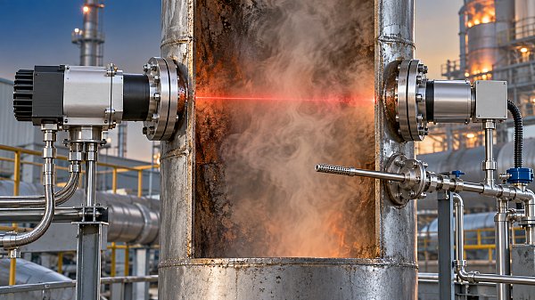
 When does a laser gas analyzer meet stack emissions monitoring needs?Laser gas analyzer for stack emissions: learn when it delivers fast, reliable data, how to assess installation risks, and what to verify for CEMS compliance.
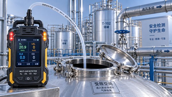
 How to select a hazardous gas analyzer for confined spacesHazardous gas analyzer selection for confined spaces: compare sensors, sampling, certifications, alarms, and maintenance to protect workers and choose with confidence.
 When is a single gas analyzer sufficient for workplace safety monitoring?Discover when a single gas analyzer delivers reliable workplace safety monitoring, and learn the key limits, calibration needs, and risks that require broader detection.
 How to choose an ambient gas analyzer for low-level leak detectionAmbient gas analyzer selection for low-level leak detection: compare sensitivity, cross-sensitivity, sampling design, alarms, and calibration for reliable site performance.
 How to tell when an oxygen sensor needs replacementOxygen sensor replacement signs explained: learn how live data, fault codes, wiring checks, and exhaust inspections pinpoint the real issue before you buy.
 How laser gas analyzers improve combustion control in steel furnacesLaser gas analyzer for steel industry applications delivers fast in-situ O₂ and CO data to optimize furnace combustion, cut fuel waste, and improve steel heating stability.
 How to verify whether explosion proof equipment meets site requirementsExplosion proof equipment verification made practical: match zones, gas or dust groups, temperature classes, certificates, and installation conditions for confident compliance.
 How industrial gas analysis helps detect contamination before releaseIndustrial Gas Analysis helps detect moisture, oil, oxygen, and toxic contaminants before release—protecting processes, ensuring compliance, and reducing costly risks.
 When is electrochemistry detection the right choice for water analysis?Electrochemistry detection for water analysis: learn when fast, reliable monitoring of ions, chlorine, pH, and more delivers actionable results.
 How industrial standards reduce quality risks in supplier selectionIndustrial Standard guidance helps quality and safety managers reduce supplier risks, verify compliance, strengthen traceability, and build resilient instrumentation supply chains.
 When does a multi-component system reduce installation complexity?Multi component systems reduce installation complexity when they eliminate field interfaces, streamline commissioning, and provide proven compatibility. Learn how to assess total cost and supplier accountability.
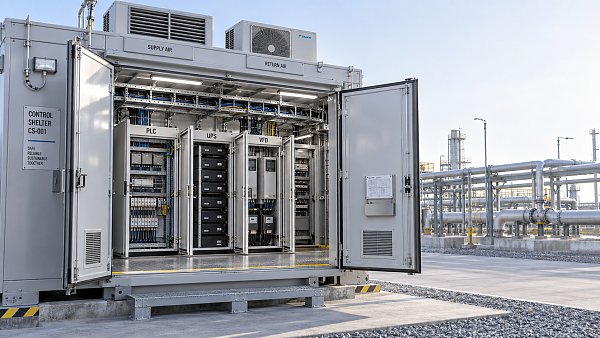
 How to size an industrial control shelter for outdoor equipmentIndustrial control shelter sizing guide: optimize layout, HVAC, access, safety, and expansion space for reliable outdoor equipment operations.
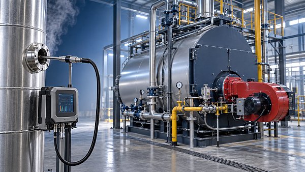
 How flue analysis helps verify combustion efficiencyFlue analysis verifies combustion efficiency by assessing O2, CO, CO2, and stack temperature to identify excess air, incomplete combustion, and heat losses.
 How to select industrial gas detectors for confined spacesIndustrial gas detectors for confined spaces: learn how to match sensors, sampling methods, alarms, and certifications to real atmospheric hazards.
 When does a laser oxygen analyzer outperform zirconia sensors?Laser oxygen analyzer vs. zirconia sensors: compare speed, selectivity, maintenance, gas chemistry, and installation needs to choose the right oxygen measurement solution.
 How to select a percent range analyzer for process measurementsPercent range analyzer selection made practical: compare accuracy, sample systems, calibration, gas matrix, integration, and lifecycle cost for reliable process measurements.
 How explosion proof analysis verifies safe equipment for hazardous areasExplosion proof analysis verifies hazardous-area equipment by matching certifications, temperature ratings, installation details, and inspection controls for safer compliance.
 When does fixed gas detection need point sensors instead of open-path monitoring?Fixed gas detection: discover when point sensors outperform open-path monitoring for predictable leaks, enclosed zones, local alarms, and safer design decisions.
 How to choose industrial metrology systems for tight-tolerance partsIndustrial metrology guide for tight-tolerance parts: compare CMMs, optical scanners, gauges, uncertainty, workflow, and traceable inspection strategies.
 How process metrology reduces measurement variation in productionProcess metrology reduces production measurement variation by improving traceability, uncertainty control, calibration, and reliable quality decisions.
 How to select an industrial monitoring analyzer for harsh environmentsIndustrial monitoring analyzer selection for harsh environments: evaluate sampling, durability, hazardous-area compliance, accuracy, maintenance, and data reliability.
 How calibration intervals affect test and measurement equipment accuracyTest and measurement equipment calibration intervals directly affect accuracy, risk, compliance, and uptime. Learn how to set evidence-based schedules that protect critical decisions.
 When does process gas monitoring need continuous measurement?Process gas monitoring needs continuous measurement when rapid changes threaten safety, quality, compliance, or uptime. Learn how to specify reliable, actionable monitoring systems.
 How to prevent false alarms in power plant instrumentationPower plant instrumentation guide: prevent false alarms with reliable signal checks, smarter alarm settings, mode-based control, and actionable operator responses.
 How fixed gas detectors help prevent leaks in enclosed workspacesFixed gas detectors provide continuous leak monitoring in enclosed workspaces, enabling faster alarms, safer responses, and stronger protection for people and processes.
 How industrial gas analysis helps detect process contamination earlyIndustrial Gas Analysis helps detect oxygen, moisture, and hydrocarbon contamination early, enabling faster fault isolation, safer operations, and stronger process control.
 What drives environmental compliance continuous monitoring setup cost?Environmental compliance continuous monitoring setup cost: uncover hidden expenses, compare bids accurately, and build a reliable, audit-ready system.
 How to select gas analysis equipment for continuous emissions monitoringGas analysis equipment selection guide for reliable continuous emissions monitoring—compare technologies, sampling, calibration, compliance, and maintenance needs.
 What detection limit is needed for NH3 environmental monitoring?High accuracy NH3 analyzer for environmental monitoring: learn how to set the right detection limit, improve sampling reliability, and make defensible decisions.
 How to select a NOX analyzer for power plant emissions complianceNOX analyzer for power plant emissions: learn how to select a compliant, reliable CEMS solution with the right range, sample handling, calibration, and data integrity.
 How to evaluate a laser gas analyzer manufacturer in GermanyLaser gas analyzer manufacturer in Germany: compare accuracy, sample handling, interference control, calibration, and service to select a reliable solution.
 How does a flue gas analyzer maintain accuracy in wet stack gas?Flue gas analyzer accuracy in wet stack gas depends on heated sampling, moisture correction, reliable sensors, and calibration. Explore key selection tips.



Search Categories
Search Categories
- Smart Meters & Power Quality
- Transformer Gas Analyzers
- BESS Thermal Runaway Detectors
- Energy, Power & Smart Grid Monitoring
- Optical Profilers & CMM
- Ultrasonic & X-Ray NDT
- Calibration Standards
- Precision Metrology & NDT
- Water Quality Analyzers
- CEMS & VOCs Monitors
- Price Trends
- Import & Export Updates
- Market Trends
- Industry News
- Industry Insights
Latest Article
- When does a laser gas analyzer meet stack emissions monitoring needs?Laser gas analyzer for stack emissions: learn when it delivers fast, reliable data, how to assess installation risks, and what to verify for CEMS compliance.Posted by:
- How to select a hazardous gas analyzer for confined spacesHazardous gas analyzer selection for confined spaces: compare sensors, sampling, certifications, alarms, and maintenance to protect workers and choose with confidence.Posted by:
- When is a single gas analyzer sufficient for workplace safety monitoring?Discover when a single gas analyzer delivers reliable workplace safety monitoring, and learn the key limits, calibration needs, and risks that require broader detection.Posted by:
Please give us a message
