Where to Place CO Analyzers for Effective Parking Garage Ventilation


Place a CO analyzer for parking garage ventilation where it can measure representative air in the area its ventilation controls serve, with additional coverage for places where exhaust may accumulate. Avoid locations directly exposed to fresh-air discharge, isolated behind obstructions, or selected only because wiring is convenient. Mounting height, sensor spacing, and installation details should follow the selected equipment’s instructions and the applicable garage ventilation requirements.
A garage can have adequate fan capacity and still respond late to rising carbon monoxide if its sensors miss the affected area. Effective placement connects three things: where vehicles produce exhaust, how air moves through the garage, and which fans or dampers respond to each reading. That connection should be established before installation locations are finalized.
Start with the ventilation zones and vehicle routes
Use a garage plan showing supply-air openings, exhaust points, ramps, partitions, pedestrian routes, and ventilation control zones. Add the places where vehicles are likely to queue, idle, or start repeatedly. Entry barriers, payment gates, pickup areas, and congested ramps deserve attention because vehicle activity can differ substantially from the surrounding parking bays.
Each independently controlled ventilation zone needs monitoring that represents conditions within it, with coverage established by the design requirements and sensor manufacturer. A sensor on one level should not be assumed to represent another level simply because an open ramp connects them. Similarly, one reading may not adequately represent two sections separated by walls or other barriers to airflow.
Distinguish between a representative monitoring location and a local accumulation point. The first supports routine ventilation control across an area. The second addresses a place where exhaust may build up faster than elsewhere. Depending on the layout, both may need monitoring. Moving the only sensor toward a busy gate could improve detection there while leaving a sheltered parking section poorly represented.
For example, a garage level with an open central aisle and a parking pocket behind a partition should be assessed as two different airflow conditions. Even if both areas use the same exhaust fan, the central sensor may respond slowly to pollution in the pocket. That can justify another sensing point within the existing control zone.
Choose the height from the sensing requirements, not a gas-density shortcut
Carbon monoxide mixes readily with air. Vehicle exhaust also enters the garage as a warm, moving plume, while fans, drafts, and vehicle movement affect its distribution. Placing every CO detector at the ceiling because exhaust is warm, or near the floor because the source is a tailpipe, oversimplifies what happens inside the space.
For ambient CO monitoring, manufacturers commonly specify installation around the occupied breathing zone, although the permitted mounting position depends on the detector and application. Use the installation instructions to set the actual height, orientation, and clearances. Where the design requirements specify a mounting arrangement, select equipment compatible with that arrangement.
Measure the height to the sensing inlet or the reference point identified in the manual. The center of an enclosure is not necessarily where gas enters. This matters when different detector models appear on the same installation drawing or when a protective housing changes the position of the sensing opening.
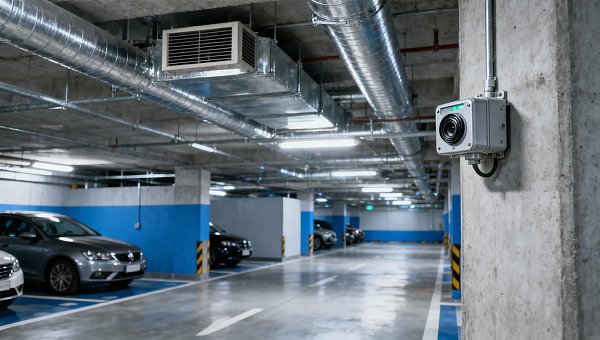
A wall or column can provide a practical mounting surface if air can reach the sensor freely. Avoid recesses, solid covers, and locations behind signage or stored equipment. Where vehicles could strike the unit, use suitable impact protection that preserves airflow and access for calibration.
Read the airflow before selecting the exact mounting point
A sensor near a fresh-air outlet may repeatedly sample diluted air while concentrations rise farther into the garage. A device next to an entrance can experience a similar problem when outdoor air sweeps through the opening. These locations can look attractive on a drawing because they are accessible, yet provide an incomplete picture of occupied areas.
An exhaust grille requires a different judgment. Air arriving there may contain contaminants collected from a broad area, but the reading may conceal uneven conditions upstream. Whether such a location is useful depends on the air distribution and monitoring purpose. It should not automatically replace sensing within the occupied zone.
Pay particular attention to sheltered corners, deep parking rows, enclosed ramp sections, and areas separated by substantial partitions. Air may pass along the main aisle without effectively sweeping these spaces. Structural features can therefore matter more than the geometric distance between detectors.
Jet fans add another consideration. Their airflow patterns change when fans switch on, change speed, or operate in different combinations. Positioning a detector directly in a high-velocity discharge path may make its reading heavily dependent on fan operation. Assess whether the sensor represents the intended area both before ventilation increases and while the system runs.
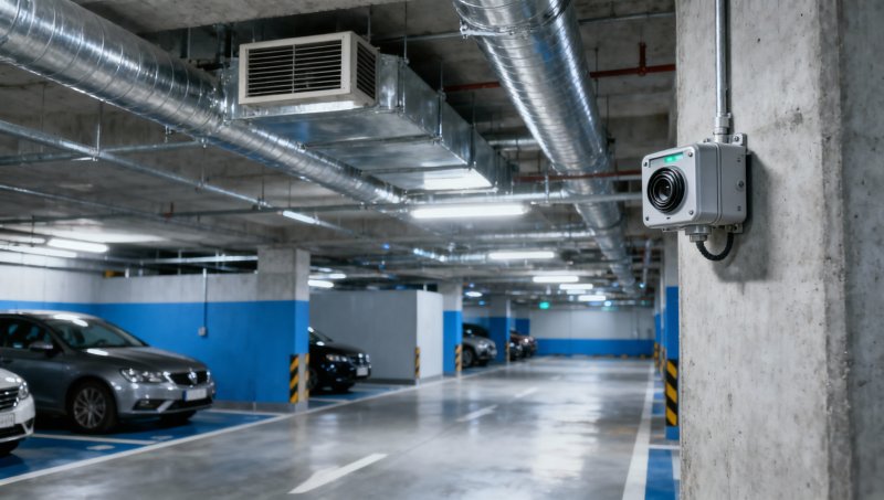
A useful placement drawing shows sensing points alongside vehicle routes, airflow directions, partitions, and control-zone boundaries. It should make the reason for each location visible: representative coverage, a sheltered area, a queueing location, or another defined concern.
Avoid direct tailpipe exposure unless the monitoring design specifically calls for it. A sensor immediately behind a parking position can receive concentrated exhaust pulses that do not represent the surrounding air. The aim is to detect developing conditions in the monitored space while avoiding an installation dominated by a single vehicle’s exhaust jet.
Determine sensor quantity from coverage and layout together
There is no universal sensor count that suits every garage of a given floor area. Manufacturer coverage guidance and applicable design requirements establish the basis for spacing, but the layout determines whether that spacing provides meaningful monitoring. A nominal coverage area does not establish reliable detection through a partition or into a poorly ventilated pocket.
Use the following sequence when developing the layout:
- Divide the garage into ventilation control zones and identify distinct airflow areas within them.
- Apply the selected detector’s spacing and coverage instructions, together with the project’s installation requirements.
- Add sensing points where barriers, traffic concentrations, or sheltered areas leave a gap in representative monitoring.
- Check that every point can be accessed, protected, connected, and maintained at the intended location.
Do not remove a sensor solely because its coverage overlaps another sensor on a plan. The overlap may be useful if the devices monitor different airflow conditions. Conversely, two nearby detectors in the same fresh-air stream may add little value while another part of the zone remains inadequately monitored.
For complicated geometries or jet-fan arrangements, airflow analysis can help evaluate the proposed locations. Its usefulness depends on whether it represents relevant operating modes, including low ventilation and peak traffic conditions. A full-speed airflow pattern alone may not explain where CO accumulates before demand-controlled ventilation responds.
Match each reading to a defined ventilation response
Placement and control logic need to be reviewed together. A correctly located sensor provides limited benefit if it activates the wrong fan group, reports to the wrong zone, or appears only on a display without initiating the required response.
The control sequence should identify which readings affect each ventilation zone, how ventilation stages change, and what happens when a sensor develops a fault. It should also distinguish normal ventilation demand from alarm functions where these have separate requirements. Fan-start thresholds, alarm thresholds, and their delays should come from the project’s approved design basis.
When several detectors serve one zone, consider how the controller combines their readings. An arithmetic average can dilute a high reading from one affected area with low readings elsewhere. A strategy based on the highest valid reading can respond to a local increase, but it must also handle faults and abnormal signals appropriately. The chosen method needs to match the garage’s coverage and control objectives.
Loss of communication or sensor failure should produce a defined fault response. A missing reading must not silently become a clean-air indication. The design should state the required ventilation fallback and fault notification so that commissioning can test both.
Select equipment that supports the intended installation
In garage applications, the term “CO analyzer” often refers to a fixed ambient CO detector or transmitter connected to a ventilation controller. A process analyzer intended for a conditioned sample stream is a different installation. Confirm whether the selected equipment measures air directly at the enclosure or requires an external sampling arrangement.
With a sampling system, the sample inlet determines where the air is measured. Tubing, sample flow, and transport time affect how quickly a change reaches the analyzer. Locating the analyzer cabinet conveniently does not resolve sample-point placement or response time.
For fixed detectors, compare equipment against the actual garage conditions: temperature, humidity, condensation, washdown exposure, dust, and possible impact. Check the sensing inlet arrangement, calibration procedure, replacement access, and controller interface. A unit that is difficult to service at its installed height or position can create avoidable maintenance problems.
CO monitoring also has a defined scope. Where diesel traffic or the applicable design requirements call for nitrogen dioxide monitoring, a CO reading alone does not establish NO₂ conditions. Any additional gas sensor needs its own placement review and control requirements; a shared enclosure should not obscure those differences.
Commission the location as well as the detector
Commissioning should verify the complete path from gas detection to ventilation operation. Applying suitable test gas demonstrates sensor response and can exercise the control sequence. It does not demonstrate that exhaust from every part of the garage will reach that sensor promptly.
Review the installed layout during an airflow walkthrough, supported by appropriate airflow observations where needed. Check conditions with fans at their normal low operating state and at increased ventilation. Doors, gates, dampers, and jet fans can change the paths that carried air across the original design drawing.
The handover checks should include:
- Installed location, sensing height, orientation, and unobstructed air access.
- Sensor identification, controller address, and assignment to the correct ventilation zone.
- Calibration or verification using the manufacturer’s specified procedure.
- Fan and damper response, alarm operation where provided, and recovery behavior.
- Fault response to loss of signal, communication, or detector operation.
- Access for future testing, sensor replacement, and inspection.
Early operating trends can reveal issues that a single functional test misses. Repeatedly low readings at one point while nearby detectors rise may warrant an airflow and location review. Short spikes associated with one parking position may indicate direct plume exposure. Investigate those patterns before changing thresholds or adding delays to suppress them.
Keep the final sensor plan with the ventilation control documentation. Record why each location was selected, which equipment it controls, and how it can be maintained. If barriers, parking arrangements, or traffic routes change later, that record provides a practical basis for reviewing coverage. The installation is ready for handover when the sensing locations, airflow behavior, and control response have been checked as one working system.
Recommended for You
 How to set industrial calibration intervals based on equipment riskSet industrial calibration intervals based on equipment risk, drift, and as-found data. Learn when to shorten or extend schedules to improve reliability and avoid unnecessary costs.
 How to choose electrochemical analyzers for low-current measurementsCompare electrochemical analyzers for precise low-current measurements. Learn how noise, leakage, bandwidth, and real-cell testing help you choose the right instrument.
 What tolerance does a custom gas mixture need for calibration?Choose the right custom gas tolerance for calibration. Learn how blending tolerance, certified uncertainty, and stability affect accuracy—and avoid paying for precision you don’t need.
 How condensation affects stack detector readings in wet flue gasStack detector readings can drift when wet flue gas condenses. Learn how to identify moisture interference, prevent sample losses, and improve emissions monitoring reliability.
 How to prevent condensation in a CO2 analyzer sampling systemPrevent condensation in your CO2 analyzer sampling system. Learn how to control dew point, eliminate cold spots, and manage moisture for reliable readings and fewer costly disruptions.
 How to verify accuracy claims for industrial quality analyzersVerify accuracy claims for industrial quality analyzers with calibration checks, independent testing, and clear acceptance criteria. Learn how to reduce risk and buy with confidence.
 How to calculate cooling loads for an industrial analyzer shelterSize industrial analyzer shelter cooling with confidence. Learn to calculate equipment heat, solar gains, and ventilation loads, then select HVAC capacity for reliable analyzer performance.
 Where to Place CO Analyzers for Effective Parking Garage VentilationOptimize your CO analyzer for parking garage ventilation with practical placement tips. Learn how sensor height, airflow, and zone coverage support timely detection and effective fan control.
 NDIR vs. FTIR Gas Analyzers: Which Fits Your Environmental Research?Find the right infrared gas analyzer for environmental research. Compare NDIR vs. FTIR on sensitivity, gas coverage, sampling needs, and cost to choose confidently for your study.
 Oxygen Analyzers for Diving: Calibration Checks Before Nitrox BlendingUsing an oxygen analyzer for diving applications? Discover essential calibration, sensor, and sampling checks before nitrox blending to support reliable readings.
 How Paramagnetic Oxygen Analyzers Work and Why Sample Pressure MattersLearn how a paramagnetic oxygen analyzer works, why sample pressure affects accuracy, and what to check in compensation and calibration before choosing your system.
 How Much Does a Complete CEMS Integration Project Typically Cost?How much does a complete CEMS integration project typically cost? Explore budget ranges, hidden installation costs, and compliance needs to compare quotes and plan confidently.
 What Is the Typical Response Time for Industrial Air Monitors?What is the typical response time for industrial air monitors? Explore T90, sampling delays, and alarm settings to compare performance and choose the right monitor with confidence.
 Do Regulatory Monitoring Systems Need Third-Party Certification?Do regulatory monitoring systems need third-party certification? Learn when it is required, what certificates prove, and how to verify compliance before buying.
 How Do You Choose Wired or Wireless for Stack Monitoring?Learn how to choose between wired and wireless for stack monitoring. Compare reliability, lifecycle costs, and data recovery to find the right CEMS setup for your site.
 What Happens When Combustible Gas Sensor Calibration Is Overdue?What happens if combustible gas sensor is not recalibrated on time? Discover the risks of inaccurate readings and missed alarms, plus steps to restore reliable protection.
 Can One Multi-Gas Detector Replace Four Separate Analyzers?Find out: can a single multi-gas detector replace four separate analyzers? Compare accuracy, safety, compliance, and lifetime costs to make a confident buying decision.
 Industrial Safety vs. Emission Monitoring: What Are the Differences?What are the main differences between industrial safety and emission monitoring? Compare goals, sensors, response times, and compliance needs to choose the right systems for your facility.
 Is Remote Monitoring Worth the Cost for Small Emission Sources?Is it worth investing in remote monitoring for small emission sources? Compare costs, compliance needs, and potential savings to choose the right solution for your operation.
 How Do You Handle Analyzer Failure During an Environmental Audit?Learn how to handle analyzer failure during environmental compliance audit procedures. Protect evidence, verify data, and restore monitoring with this practical response guide.
 Do VOC Monitors Require Explosion-Proof Certification?Does VOC monitoring require explosion-proof certification? Learn when approval is needed, compare ATEX and IECEx, and choose the right monitor for your site.
 How sample conditioning affects accuracy in petrochemical analyzersImprove accuracy in petrochemical analyzers with smarter sample conditioning. Discover how phase control, filtration, and transport design prevent bias and deliver reliable process data.
 How to troubleshoot sensor drift in industrial gas detectorsIndustrial gas detectors showing sensor drift? Learn how to verify calibration gas, identify root causes, and determine when sensor replacement is needed for reliable monitoring.
 How to judge whether a competitive price reflects real valueCompetitive Price: learn how to compare scope, compliance, performance, and lifecycle costs to identify real value, reduce risk, and make smarter purchasing decisions.
 When custom gas analysis is the right fit for complex process streamsCustom gas analysis for complex process streams: learn when tailored sampling, interference control, and reliable measurement design deliver confident decisions.
 When does a laser gas analyzer meet stack emissions monitoring needs?Laser gas analyzer for stack emissions: learn when it delivers fast, reliable data, how to assess installation risks, and what to verify for CEMS compliance.
 How to select a hazardous gas analyzer for confined spacesHazardous gas analyzer selection for confined spaces: compare sensors, sampling, certifications, alarms, and maintenance to protect workers and choose with confidence.
 When is a single gas analyzer sufficient for workplace safety monitoring?Discover when a single gas analyzer delivers reliable workplace safety monitoring, and learn the key limits, calibration needs, and risks that require broader detection.
 How to choose an ambient gas analyzer for low-level leak detectionAmbient gas analyzer selection for low-level leak detection: compare sensitivity, cross-sensitivity, sampling design, alarms, and calibration for reliable site performance.
 How to tell when an oxygen sensor needs replacementOxygen sensor replacement signs explained: learn how live data, fault codes, wiring checks, and exhaust inspections pinpoint the real issue before you buy.
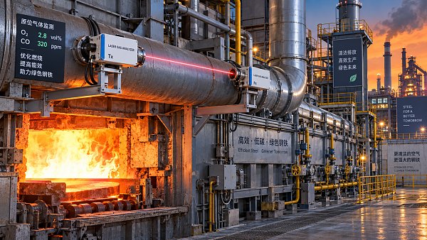
 How laser gas analyzers improve combustion control in steel furnacesLaser gas analyzer for steel industry applications delivers fast in-situ O₂ and CO data to optimize furnace combustion, cut fuel waste, and improve steel heating stability.
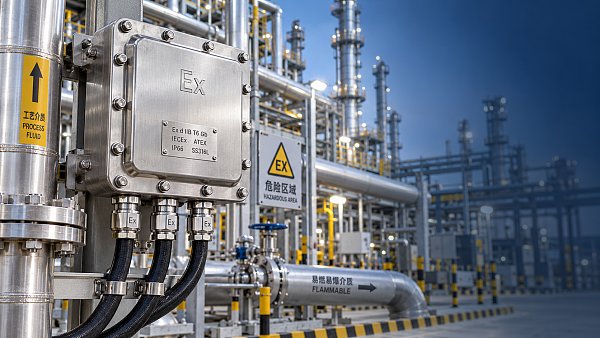
 How to verify whether explosion proof equipment meets site requirementsExplosion proof equipment verification made practical: match zones, gas or dust groups, temperature classes, certificates, and installation conditions for confident compliance.



Search Categories
Search Categories
- Smart Meters & Power Quality
- Transformer Gas Analyzers
- BESS Thermal Runaway Detectors
- Energy, Power & Smart Grid Monitoring
- Optical Profilers & CMM
- Ultrasonic & X-Ray NDT
- Calibration Standards
- Precision Metrology & NDT
- Water Quality Analyzers
- CEMS & VOCs Monitors
- Price Trends
- Import & Export Updates
- Market Trends
- Industry News
- Industry Insights
Latest Article
- How to set industrial calibration intervals based on equipment riskSet industrial calibration intervals based on equipment risk, drift, and as-found data. Learn when to shorten or extend schedules to improve reliability and avoid unnecessary costs.Posted by:
- How to choose electrochemical analyzers for low-current measurementsCompare electrochemical analyzers for precise low-current measurements. Learn how noise, leakage, bandwidth, and real-cell testing help you choose the right instrument.Posted by:
- What tolerance does a custom gas mixture need for calibration?Choose the right custom gas tolerance for calibration. Learn how blending tolerance, certified uncertainty, and stability affect accuracy—and avoid paying for precision you don’t need.Posted by:
Please give us a message