
How to calculate cooling loads for an industrial analyzer shelter


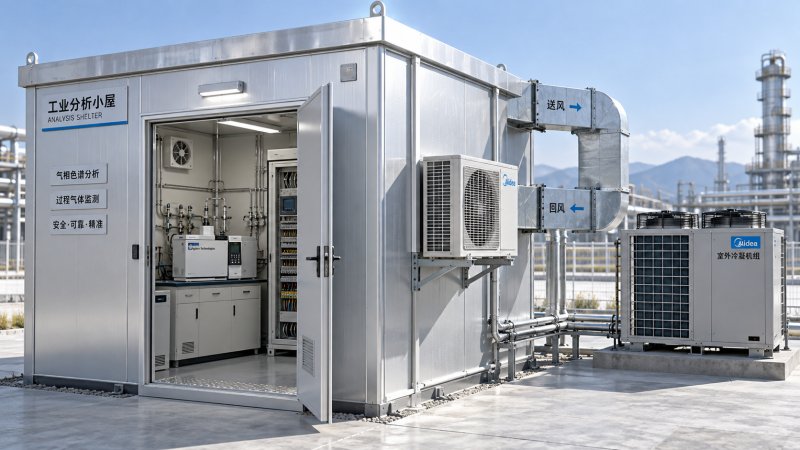
Calculate the cooling load for an industrial analyzer shelter by adding equipment heat, solar and envelope gains, outdoor-air loads, and smaller contributions from lighting and occupants. Separate sensible heat, which raises air temperature, from latent heat, which comes from moisture. Then select an HVAC system that can meet both loads at the actual site conditions.
Floor area alone is a poor sizing basis. A compact shelter containing heated sample systems, gas chromatographs, and electrical cabinets can require more cooling than a larger enclosure with fewer instruments. Ventilation can also become a major load when hot, humid outdoor air enters continuously.
A defensible calculation connects every load to a documented input and operating condition. The result should show how much heat must be removed, when the peak occurs, and whether the selected system can maintain the required environment during normal operation and equipment failures.
Define the operating conditions before calculating heat gains
Start with the temperature and humidity limits of the installed analyzers, sample-conditioning equipment, and electronics. An instrument’s maximum allowable ambient temperature is an operating boundary, not necessarily a suitable room setpoint. Temperature stability may affect measurement performance, while a cool room can still contain overheated cabinets if airflow is poor.
Choose an indoor design condition that supports the most restrictive equipment requirement. Include any limits on temperature variation, relative humidity, and condensation. These requirements should come from equipment documentation and the process application.
For outdoor conditions, use the project’s climatic design basis. Dry-bulb temperature governs much of the sensible load; humidity ratio or wet-bulb temperature is needed to assess moisture removal. Evaluate representative coincident weather conditions rather than combining unrelated maximum temperature and humidity values. A hot afternoon may govern sensible capacity, while a more humid period may govern dehumidification.
Record shelter dimensions, orientation, wall and roof construction, insulation, doors, windows, shading, and installed equipment. Also define the outdoor-air supply, exhaust arrangements, pressurization requirements, and expected door use. Without these inputs, a cooling-capacity figure cannot be meaningfully compared between suppliers.
Build an equipment heat schedule
Internal equipment often provides a large, continuous heat load. List each analyzer and auxiliary device, its quantity, operating mode, and heat released into the shelter. Include sample pumps, heated cabinets, computers, network equipment, power supplies, and any UPS installed inside.
Use manufacturer heat-dissipation data where available. Electrical nameplate power can be misleading because it may represent maximum input, startup demand, or a rating covering optional accessories. Conversely, counting only the analyzer can miss substantial heat from its sample-handling system.
For equipment whose electrical input is ultimately dissipated inside the room, operating electrical power is a reasonable heat-gain estimate. Adjust that assumption when energy leaves through an external cooling circuit, discharged sample stream, or another boundary.
Sample coolers require particular care. A refrigeration unit with its condenser inside the shelter rejects both the heat removed from the sample and the compressor’s input energy into the room. A remotely located condenser changes that balance. Hot sample lines can also introduce process heat that is absent from an electrical equipment schedule.
Add the simultaneous equipment loads:
Qequipment = Σ(n × q × f)
Here, n is quantity, q is heat released per device, and f is a justified operating or simultaneity factor. Keep units consistent. Do not apply a general diversity reduction to equipment that operates continuously. For cycling heaters, distinguish average room load from short-duration peaks that could affect nearby instruments.
Calculate envelope heat transfer and solar gain together
For a surface without solar effects, the basic steady-state transmission calculation is:
Qtransmission = U × A × (Toutside − Tinside)
With U in W/(m²·K), area A in m², and temperature difference in K, the result is watts. Calculate walls, roof, doors, and other boundaries separately. Use the complete assembly’s thermal performance, including thermal bridges where significant, rather than the insulation material value alone.
Solar exposure changes the calculation. A sunlit metal roof can reach a temperature above the outdoor air temperature, so an ambient-temperature calculation alone can underestimate heat gain. Orientation, surface absorptance, shading, roof construction, and time of day all matter.
For an initial calculation, an appropriate sol-air temperature method can represent outdoor temperature and absorbed solar radiation together. For detailed design, an established heat-balance or radiant time-series method can account for solar timing and heat storage. Use one consistent method: adding a separate opaque-surface solar allowance after using sol-air temperature can count the same gain twice.
Calculate glazing conduction and transmitted solar gain separately if windows are present. Treat the floor according to its actual boundary condition, such as a ground-supported slab or an elevated floor exposed to outdoor air.
A reflective finish or ventilated sunshade can reduce solar gain, but only credit features included in the specified construction. Assess the coincident shelter peak; every wall’s individual solar maximum does not occur at the same time.
Account for ventilation without double-counting airflow
Outdoor air can add both sensible and latent load. The sensible component is:
Qair,sensible = ρ × cp × V̇ × (Toutside − Tinside)
Here, ρ is air density, cp is specific heat, and V̇ is outdoor-air volume flow. Using kg/m³, kJ/(kg·K), and m³/s gives a result in kW. Use air properties suitable for the site, especially where altitude affects density.
The total outdoor-air load can be calculated from moist-air enthalpy:
Qair,total = ṁdry air × (houtside − hinside)
Use dry-air mass flow in kg/s and enthalpy in kJ/kg of dry air to obtain kW. The enthalpy difference includes sensible and latent components. Do not add the sensible calculation to this total. Split the total consistently using psychrometric calculations when checking sensible and moisture-removal capacity.
Determine outdoor airflow from the ventilation and safety design. Recirculated air is not outdoor air: moving more air through an evaporator does not create the same weather-related load as bringing fresh air into the shelter.
Map supply, exhaust, pressure-relief flow, and leakage as one air balance. If supplied outdoor air replaces exhausted air and maintains positive pressure, do not count that exhaust replacement again as a separate infiltration load. Door opening creates a different, intermittent exchange and should reflect realistic access frequency and recovery requirements.
Also distinguish continuous ventilation from temporary purging. They may have different airflow rates and operating sequences. Size cooling for the modes that require temperature control rather than assuming all airflow modes run simultaneously.
Assemble loads by operating scenario
For each relevant operating condition, calculate:
Qsensible = equipment heat + envelope and solar gain + outdoor-air sensible load + lighting + occupant sensible heat + applicable fan heat
Qlatent = outdoor-air moisture load + occupant moisture + other moisture sources
Qtotal = Qsensible + Qlatent
Maintain separate sensible and latent totals throughout the worksheet. Two shelters with the same total load can need different HVAC selections if one is dominated by instrument heat and the other by humid ventilation air.
Evaluate normal operation, hot-weather operation, humid-weather operation, and any maintenance or startup condition that materially changes demand. These are calculation scenarios, not additions to one oversized total. Continuous analyzer operation may coincide with peak roof gain; occasional occupancy may warrant a separate check.
Keep future expansion and design uncertainty visible. If additional analyzer positions are planned, assign their expected heat load explicitly. An unexplained margin can conceal missing inputs or duplicate conservatism already included elsewhere.
Thermal storage can soften brief peaks, but it does not eliminate sustained heat. Where temporary temperatures matter, assess heat accumulation and recovery over time rather than relying only on a steady-state sum.
Select HVAC capacity at the shelter’s actual conditions
The calculated load is not automatically the required catalogue rating. Obtain cooling performance at the specified outdoor temperature, indoor condition, and airflow. Available capacity can change with those conditions, so a unit’s nominal rating is insufficient for selection.
Check both total and sensible capacity. A system can satisfy total demand yet lack enough sensible capacity for an equipment-heavy shelter. In a humid location, it may instead struggle to remove moisture while maintaining temperature. The sensible heat ratio—sensible load divided by total load—helps describe demand, but the supplier’s capacity data must demonstrate the match.
Compare load and capacity at the same boundary. Gross coil capacity may require a deduction for supply-fan heat, while net capacity may already include it. Similarly, identify whether outdoor air is conditioned by the shelter unit or by a separate system.
Air distribution also affects performance. Confirm clear supply and return paths around racks and cabinets, and place control sensors where they represent equipment conditions. A satisfactory room-average temperature can conceal a hot analyzer inlet.
Avoid solving uncertainty through excessive oversizing. Short cycling can weaken temperature control and moisture removal. Capacity modulation, staged units, or an appropriate control sequence may handle changing loads more effectively.
Make safety, redundancy, and acceptance requirements explicit
Ventilation and pressurization requirements must remain part of the cooling design. Do not reduce required outdoor airflow simply to obtain a smaller air conditioner. Hazardous-area classification, possible sample releases, gas detection, and the selected protection concept determine which ventilation functions and interlocks are necessary.
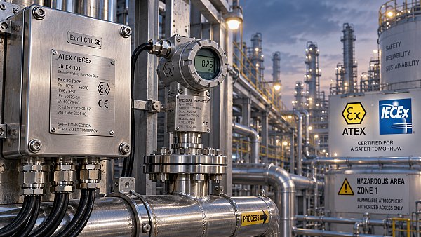
ATEX or IECEx equipment suitability, where applicable, addresses explosion-protection requirements; it does not establish adequate cooling capacity. Accepted HVAC calculation methods, including those described in ASHRAE guidance, address thermal performance. The project specification should connect these requirements without treating one as a substitute for another.
Define redundancy by the capacity available after a failure. Two units sharing the normal load do not provide full standby capacity unless the remaining unit can meet the required failure-mode load at design conditions. State the allowable temperature excursion, standby response, and whether any equipment can be safely shut down.
Finally, require a reviewable calculation package: input conditions, equipment heat schedule, envelope assumptions, air balance, sensible and latent totals, expansion allowance, and HVAC performance data. During commissioning, check temperature distribution, humidity, ventilation flow, and standby operation under representative loads. These checks connect the cooling calculation to the conditions the analyzers actually experience.
Recommended for You
 How to calculate cooling loads for an industrial analyzer shelterSize industrial analyzer shelter cooling with confidence. Learn to calculate equipment heat, solar gains, and ventilation loads, then select HVAC capacity for reliable analyzer performance.
 How sample conditioning affects accuracy in petrochemical analyzersImprove accuracy in petrochemical analyzers with smarter sample conditioning. Discover how phase control, filtration, and transport design prevent bias and deliver reliable process data.
 How to troubleshoot sensor drift in industrial gas detectorsIndustrial gas detectors showing sensor drift? Learn how to verify calibration gas, identify root causes, and determine when sensor replacement is needed for reliable monitoring.
 How to judge whether a competitive price reflects real valueCompetitive Price: learn how to compare scope, compliance, performance, and lifecycle costs to identify real value, reduce risk, and make smarter purchasing decisions.
 When custom gas analysis is the right fit for complex process streamsCustom gas analysis for complex process streams: learn when tailored sampling, interference control, and reliable measurement design deliver confident decisions.
 When does a laser gas analyzer meet stack emissions monitoring needs?Laser gas analyzer for stack emissions: learn when it delivers fast, reliable data, how to assess installation risks, and what to verify for CEMS compliance.
 How to select a hazardous gas analyzer for confined spacesHazardous gas analyzer selection for confined spaces: compare sensors, sampling, certifications, alarms, and maintenance to protect workers and choose with confidence.
 When is a single gas analyzer sufficient for workplace safety monitoring?Discover when a single gas analyzer delivers reliable workplace safety monitoring, and learn the key limits, calibration needs, and risks that require broader detection.
 How to choose an ambient gas analyzer for low-level leak detectionAmbient gas analyzer selection for low-level leak detection: compare sensitivity, cross-sensitivity, sampling design, alarms, and calibration for reliable site performance.
 How to tell when an oxygen sensor needs replacementOxygen sensor replacement signs explained: learn how live data, fault codes, wiring checks, and exhaust inspections pinpoint the real issue before you buy.
 How laser gas analyzers improve combustion control in steel furnacesLaser gas analyzer for steel industry applications delivers fast in-situ O₂ and CO data to optimize furnace combustion, cut fuel waste, and improve steel heating stability.
 How to verify whether explosion proof equipment meets site requirementsExplosion proof equipment verification made practical: match zones, gas or dust groups, temperature classes, certificates, and installation conditions for confident compliance.
 How industrial gas analysis helps detect contamination before releaseIndustrial Gas Analysis helps detect moisture, oil, oxygen, and toxic contaminants before release—protecting processes, ensuring compliance, and reducing costly risks.
 When is electrochemistry detection the right choice for water analysis?Electrochemistry detection for water analysis: learn when fast, reliable monitoring of ions, chlorine, pH, and more delivers actionable results.
 How industrial standards reduce quality risks in supplier selectionIndustrial Standard guidance helps quality and safety managers reduce supplier risks, verify compliance, strengthen traceability, and build resilient instrumentation supply chains.
 When does a multi-component system reduce installation complexity?Multi component systems reduce installation complexity when they eliminate field interfaces, streamline commissioning, and provide proven compatibility. Learn how to assess total cost and supplier accountability.
 How to size an industrial control shelter for outdoor equipmentIndustrial control shelter sizing guide: optimize layout, HVAC, access, safety, and expansion space for reliable outdoor equipment operations.
 How flue analysis helps verify combustion efficiencyFlue analysis verifies combustion efficiency by assessing O2, CO, CO2, and stack temperature to identify excess air, incomplete combustion, and heat losses.
 How to select industrial gas detectors for confined spacesIndustrial gas detectors for confined spaces: learn how to match sensors, sampling methods, alarms, and certifications to real atmospheric hazards.
 When does a laser oxygen analyzer outperform zirconia sensors?Laser oxygen analyzer vs. zirconia sensors: compare speed, selectivity, maintenance, gas chemistry, and installation needs to choose the right oxygen measurement solution.
 How to select a percent range analyzer for process measurementsPercent range analyzer selection made practical: compare accuracy, sample systems, calibration, gas matrix, integration, and lifecycle cost for reliable process measurements.
 How explosion proof analysis verifies safe equipment for hazardous areasExplosion proof analysis verifies hazardous-area equipment by matching certifications, temperature ratings, installation details, and inspection controls for safer compliance.
 When does fixed gas detection need point sensors instead of open-path monitoring?Fixed gas detection: discover when point sensors outperform open-path monitoring for predictable leaks, enclosed zones, local alarms, and safer design decisions.
 How to choose industrial metrology systems for tight-tolerance partsIndustrial metrology guide for tight-tolerance parts: compare CMMs, optical scanners, gauges, uncertainty, workflow, and traceable inspection strategies.
 How process metrology reduces measurement variation in productionProcess metrology reduces production measurement variation by improving traceability, uncertainty control, calibration, and reliable quality decisions.
 How to select an industrial monitoring analyzer for harsh environmentsIndustrial monitoring analyzer selection for harsh environments: evaluate sampling, durability, hazardous-area compliance, accuracy, maintenance, and data reliability.
 How calibration intervals affect test and measurement equipment accuracyTest and measurement equipment calibration intervals directly affect accuracy, risk, compliance, and uptime. Learn how to set evidence-based schedules that protect critical decisions.
 When does process gas monitoring need continuous measurement?Process gas monitoring needs continuous measurement when rapid changes threaten safety, quality, compliance, or uptime. Learn how to specify reliable, actionable monitoring systems.
 How to prevent false alarms in power plant instrumentationPower plant instrumentation guide: prevent false alarms with reliable signal checks, smarter alarm settings, mode-based control, and actionable operator responses.
 How fixed gas detectors help prevent leaks in enclosed workspacesFixed gas detectors provide continuous leak monitoring in enclosed workspaces, enabling faster alarms, safer responses, and stronger protection for people and processes.
 How industrial gas analysis helps detect process contamination earlyIndustrial Gas Analysis helps detect oxygen, moisture, and hydrocarbon contamination early, enabling faster fault isolation, safer operations, and stronger process control.
 What drives environmental compliance continuous monitoring setup cost?Environmental compliance continuous monitoring setup cost: uncover hidden expenses, compare bids accurately, and build a reliable, audit-ready system.










Search Categories
Search Categories
- Smart Meters & Power Quality
- Transformer Gas Analyzers
- BESS Thermal Runaway Detectors
- Energy, Power & Smart Grid Monitoring
- Optical Profilers & CMM
- Ultrasonic & X-Ray NDT
- Calibration Standards
- Precision Metrology & NDT
- Water Quality Analyzers
- CEMS & VOCs Monitors
- Price Trends
- Import & Export Updates
- Market Trends
- Industry News
- Industry Insights
Latest Article
- How to calculate cooling loads for an industrial analyzer shelterSize industrial analyzer shelter cooling with confidence. Learn to calculate equipment heat, solar gains, and ventilation loads, then select HVAC capacity for reliable analyzer performance.Posted by:
- How sample conditioning affects accuracy in petrochemical analyzersImprove accuracy in petrochemical analyzers with smarter sample conditioning. Discover how phase control, filtration, and transport design prevent bias and deliver reliable process data.Posted by:
- How to troubleshoot sensor drift in industrial gas detectorsIndustrial gas detectors showing sensor drift? Learn how to verify calibration gas, identify root causes, and determine when sensor replacement is needed for reliable monitoring.Posted by:
Please give us a message
