NH3 Monitoring in Fertilizer Plants: Where Should Leak Analyzers Be Installed?


NH3 Monitoring in Fertilizer Plants: Where Should Leak Analyzers Be Installed?
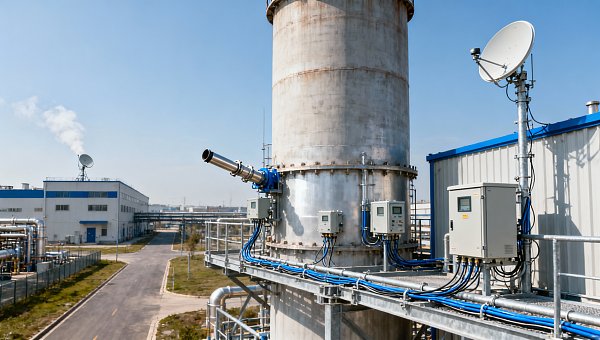
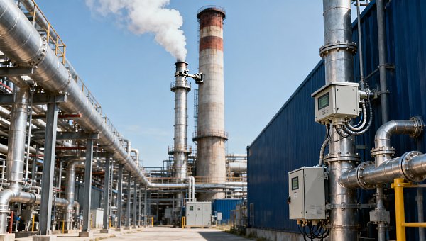
An NH3 analyzer for fertilizer production is only as effective as its placement. A reliable instrument can still give a late warning if the release travels behind a compressor skid, below a loading platform, or away from the detector with the ventilation airflow. The priority is coverage around credible leak sources and exposure routes—not simply mounting sensors above every ammonia connection.
Ammonia storage, transfer pumps, compressor seals, loading stations, and process equipment deserve attention, but they do not all need the same arrangement. This guide from Global Instrument Hub (GIH) examines how release conditions, airflow, worker access, and instrument limitations should shape detector and sampling-point locations. The final layout needs a site-specific engineering assessment; a generic mounting-height rule is not an adequate substitute.
Start with the release scenario, not the detector bracket
Before marking detector positions on a drawing, identify what could escape at each location. A small gaseous leak from a valve packing behaves differently from flashing liquid ammonia released through a damaged transfer connection. Pressure, temperature, inventory, release direction, and nearby structures influence where the plume goes and how quickly it reaches an occupied area.
Warm ammonia gas is lighter than air. That supports elevated detection in some enclosed spaces, but it does not justify installing every sensor at roof level. A cold liquid release can produce an initially dense, aerosol-containing cloud that travels close to the ground before warming and dispersing. Jet momentum can also carry a release sideways, regardless of its eventual buoyancy.
For each credible source, trace three things: the likely initial release path, the airflow or wind that could redirect it, and the people or equipment requiring protection. This exercise often reveals that source detection and exposure detection need separate points. One sensor should not be expected to provide early leak identification, room coverage, and protection of a distant walkway simultaneously.
Where coverage usually deserves priority
Storage vessels and ammonia transfer equipment
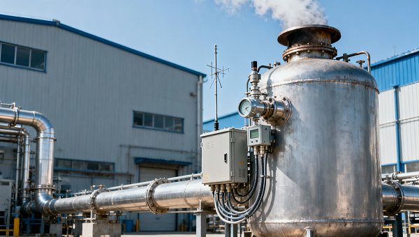
Around storage systems, concentrate on valves, liquid withdrawal connections, instrument connections, and transfer equipment rather than assuming the vessel shell is the most useful detection target. Review both pressurized and refrigerated storage arrangements according to their actual release conditions. Insulation, pipe racks, containment structures, and access platforms can redirect a cloud or create sheltered spaces.
Transfer pumps warrant coverage around seals and associated connection points, with the sensing location selected for plausible release trajectories. Do not place a detector where a liquid jet could strike it directly or where routine washdown will continually wet it. Where cold releases are credible, assess lower-level coverage as well as locations along nearby operator routes. This is a scenario-based decision, not a universal instruction to mount sensors at floor level.
Compressor seals and enclosed machinery areas
Compressors introduce a practical complication: guards, acoustic enclosures, and skid structures can separate the leak source from the room airflow. A detector outside an enclosure may miss an internal accumulation until it escapes through a particular opening. Review seal locations, enclosure extraction, and access panels before choosing positions.
An elevated detector may be appropriate for warm gaseous releases in an enclosed room, but roof pockets and separate bays may not communicate freely. Consider whether local source coverage, occupied-area coverage, and extraction-path monitoring serve different purposes. Keep instruments within their rated temperature and vibration limits; a convenient mounting point on a hot or vibrating machine may be a poor measurement location.
Loading stations and process connections
At truck or rail loading stations, hose connections, loading arms, isolation valves, and disconnect points are obvious starting locations. Less obvious are the spaces beneath platforms and the routes operators use while connecting equipment. Wind direction can change, and a parked vehicle can alter local flow. A single detector placed on the prevailing downwind side may therefore leave substantial blind spots.
Within fertilizer process areas, review ammonia feed manifolds, valve stations, equipment seals, and maintenance sampling connections. For urea, ammonium nitrate, or other ammonia-consuming units, distinguish unintended leakage from normal process emissions or authorized venting. Otherwise, a detector may repeatedly alarm during expected operations while remaining poorly positioned for the release it was intended to detect.
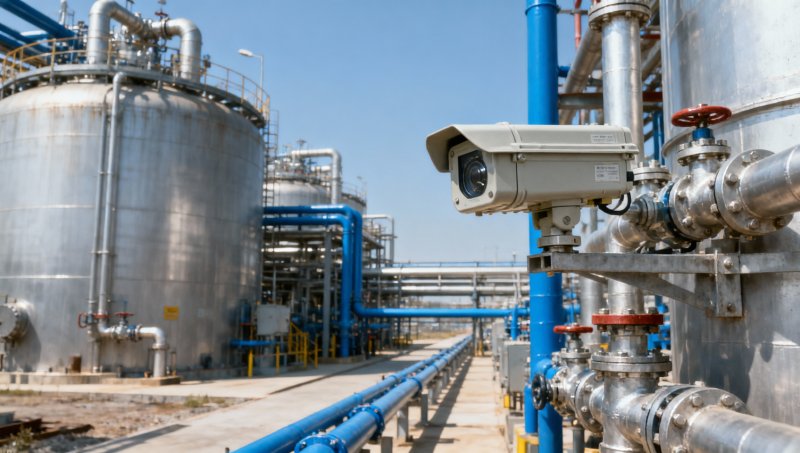
A useful layout drawing shows release sources, ventilation arrows, obstructed spaces, operator positions, and detector or sample-inlet locations together. Dots on a plan without airflow and elevation information do not demonstrate coverage.
Ventilation can help detection—or bypass it
In mechanically ventilated buildings, examine how air moves during normal operation, reduced ventilation, and fan failure. Open doors, seasonal operating changes, and temporary barriers can change that pattern. A detector near a fresh-air inlet may remain in clean air while ammonia crosses the working area toward an exhaust on the opposite wall.
An exhaust-path detector can provide useful evidence that ammonia is leaving a space, but it may not warn early enough to protect someone beside the source. It can also be affected by dilution or uneven mixing. Use exhaust monitoring as part of a coverage strategy, not automatically as a replacement for local detection.
Outdoors, avoid treating a detector as if it has a guaranteed circular detection radius. Point instruments measure gas at their sensing element; they do not detect every leak within a stated distance. Wind, turbulence, and congestion determine whether the plume intersects that point. Where consequences are significant or geometry is complex, dispersion assessment and gas-detection mapping can help test the proposed arrangement.
Choose the measurement architecture before finalizing positions
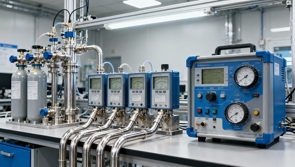
The term “analyzer” can refer to different instruments. A process analyzer measuring ammonia in a product stream is not automatically suitable for ambient leak detection. The required concentration range, response time, environmental protection, fault reporting, and intended safety function must match the application.
Fixed point detectors measure at their installed location. Extractive systems draw air from remote sampling points to an analyzer, so the inlet—not the analyzer cabinet—is the location that determines coverage. Open-path instruments measure along an optical beam and typically report a path-integrated concentration; their readings cannot be treated as directly interchangeable with local point concentrations.
These differences affect both layout and alarm design:
- Point detection: Check NH3 sensitivity, response characteristics, cross-sensitivities, and recovery after high exposure. Environmental effects depend on the sensing technology.
- Extractive monitoring: Account for sample transport, switching intervals, analyzer response, and blockage detection. Ammonia interaction with tubing surfaces and moisture can delay or distort readings.
- Open-path monitoring: Keep the beam clear of vehicles, structures, and foreseeable obstructions. Confirm performance under the site's weather and visibility conditions.
A central analyzer serving multiple inlets can simplify maintenance, but sequential sampling introduces an interval between observations at each location. That trade-off matters where rapid warning is required. Long tubing runs also need more than a nominal flow calculation: specify compatible materials and conditioning, then verify response through the complete sampling path.
Separate leak warning from exposure assessment
A source detector is intended to identify a release. It does not necessarily represent the concentration inhaled by a worker elsewhere. Likewise, a detector beside an occupied workstation may help assess local conditions without providing the earliest warning of an upstream leak. Personal monitoring may be needed for maintenance, line breaking, and other tasks where exposure locations change.
Alarm settings should follow the site's hazard assessment, applicable occupational requirements, instrument capability, and response procedures. Occupational exposure limits have defined averaging periods; they should not simply be copied into instantaneous alarm settings without review. Odor is not a dependable substitute for instrumental warning or a basis for deciding that entry is safe.
Also distinguish monitoring from protective action. An alarm, ventilation command, and automatic isolation each require a defined cause-and-effect sequence. If a detector supports a credited safety function, its placement, diagnostics, independence, and testing requirements need the corresponding engineering review. A signal displayed in the control system is not, by itself, a complete protective measure.
Prove the installation and keep it testable
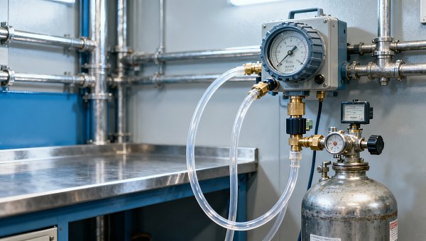
Commissioning should establish more than whether a transmitter communicates. Verify detector response, sample transport where applicable, fault indication, alarm delivery, and approved protective actions. Controlled testing must follow safe procedures; do not release ammonia into operating areas merely to see whether detectors respond. A calibration-gas test at the sensor proves instrument response, not the adequacy of site-wide coverage.
Maintain access for inspection and testing without exposing technicians to unnecessary risk. Check for dust buildup, damaged guards, blocked sample inlets, failed pumps, and changes to ventilation. Reassess coverage after new pipework, enclosures, platforms, or operating practices are introduced. A detector can remain fully calibrated while its original location becomes ineffective.
GIH's instrumentation research is most useful here as a basis for comparing technical evidence, not just instrument features. When specifying an NH3 analyzer for fertilizer production, ask suppliers to substantiate complete-system response, sampling limitations, environmental suitability, and maintenance requirements for the proposed installation.
Before approving the layout, require a clear explanation for every detection point: which release it covers, under which airflow conditions, and what action follows its alarm. Where that explanation is weak, revisit the location or monitoring architecture—not merely the number of sensors.
Recommended for You
 Can a C4H8O concentration analyzer distinguish between isomers?Can a C4H8O concentration analyzer distinguish isomers? Compare GC, FTIR and MS methods, uncover selectivity limits, and learn what to validate before choosing your instrument.
 How to identify a reliable supplier using on-time delivery recordsIdentify a Reliable Supplier by verifying on-time delivery records, original commitments, and complete shipments. Learn practical checks to reduce purchasing risk and protect your project schedule.
 How sensitive should a portable hydrogen analyzer be for lab use?Choose a portable hydrogen analyzer for laboratory use with the right quantification limit, accuracy, and range. Learn how to verify performance and avoid costly buying mistakes.
 How to set industrial calibration intervals based on equipment riskSet industrial calibration intervals based on equipment risk, drift, and as-found data. Learn when to shorten or extend schedules to improve reliability and avoid unnecessary costs.
 How to choose electrochemical analyzers for low-current measurementsCompare electrochemical analyzers for precise low-current measurements. Learn how noise, leakage, bandwidth, and real-cell testing help you choose the right instrument.
 What tolerance does a custom gas mixture need for calibration?Choose the right custom gas tolerance for calibration. Learn how blending tolerance, certified uncertainty, and stability affect accuracy—and avoid paying for precision you don’t need.
 How condensation affects stack detector readings in wet flue gasStack detector readings can drift when wet flue gas condenses. Learn how to identify moisture interference, prevent sample losses, and improve emissions monitoring reliability.
 How to prevent condensation in a CO2 analyzer sampling systemPrevent condensation in your CO2 analyzer sampling system. Learn how to control dew point, eliminate cold spots, and manage moisture for reliable readings and fewer costly disruptions.
 How to verify accuracy claims for industrial quality analyzersVerify accuracy claims for industrial quality analyzers with calibration checks, independent testing, and clear acceptance criteria. Learn how to reduce risk and buy with confidence.
 How to calculate cooling loads for an industrial analyzer shelterSize industrial analyzer shelter cooling with confidence. Learn to calculate equipment heat, solar gains, and ventilation loads, then select HVAC capacity for reliable analyzer performance.
 Hydrogen Analyzers for Energy Storage: Purity Monitoring vs. Leak DetectionChoosing a hydrogen analyzer for energy storage systems? Compare purity monitoring and leak detection to select the right sensors, improve safety, and protect fuel cell performance.
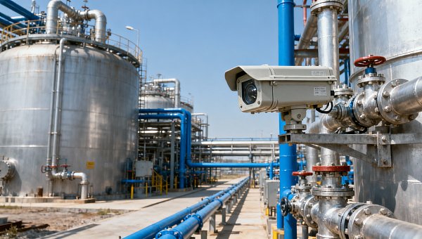
 NH3 Monitoring in Fertilizer Plants: Where Should Leak Analyzers Be Installed?NH3 analyzer for fertilizer production: discover where to place leak detectors around storage, compressors, and loading areas to reduce blind spots and improve early warning.
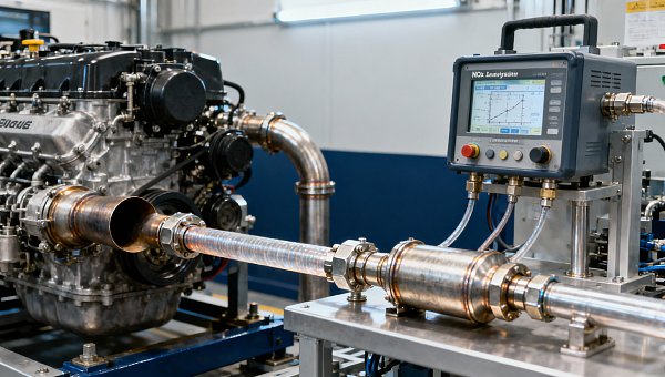
 Diesel Engine NOx Analyzers: Response Time and NO2 Conversion ExplainedChoosing a NOX analyzer for diesel engines? Learn how response time, NO2 conversion, and sampling design affect accuracy—and make a smarter, evidence-based purchase.
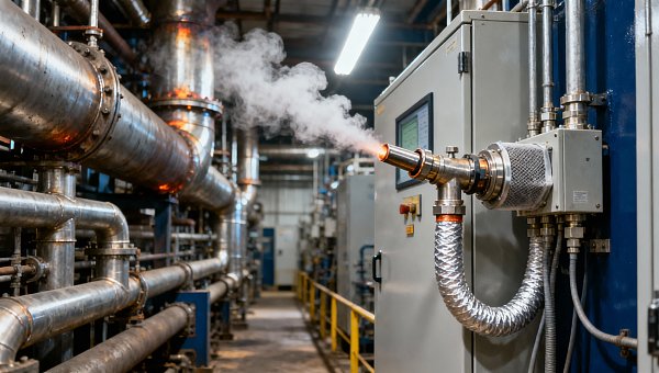
 SO2 Analyzers for Smelter Emissions: Sampling Hot, Dust-Laden Flue GasSelect an SO2 analyzer for smelting industry applications. Discover how to handle hot, dust-laden flue gas, prevent sample losses, and achieve reliable emissions monitoring.
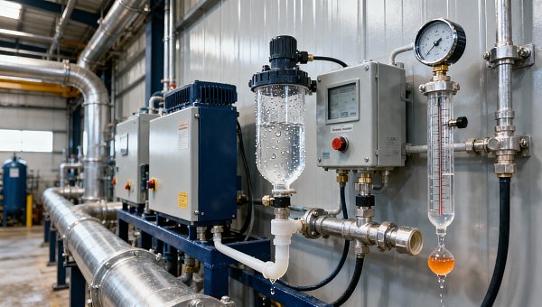
 Unstable CH4 Readings in Biogas Monitoring? Check Moisture and Sample FlowCH4 analyzer for biogas monitoring giving unstable readings? Discover how moisture, sample flow, and pressure checks help pinpoint faults and restore reliable methane measurements.
 Buying a CO2 Analyzer for Brewery Gas Recovery: Costs Beyond the Purchase PriceBuying a CO2 analyzer for brewery applications? Compare sampling, installation, calibration, and downtime costs to uncover hidden expenses and make a smarter gas recovery investment.
 Where to Place CO Analyzers for Effective Parking Garage VentilationOptimize your CO analyzer for parking garage ventilation with practical placement tips. Learn how sensor height, airflow, and zone coverage support timely detection and effective fan control.
 NDIR vs. FTIR Gas Analyzers: Which Fits Your Environmental Research?Find the right infrared gas analyzer for environmental research. Compare NDIR vs. FTIR on sensitivity, gas coverage, sampling needs, and cost to choose confidently for your study.
 Oxygen Analyzers for Diving: Calibration Checks Before Nitrox BlendingUsing an oxygen analyzer for diving applications? Discover essential calibration, sensor, and sampling checks before nitrox blending to support reliable readings.
 How Paramagnetic Oxygen Analyzers Work and Why Sample Pressure MattersLearn how a paramagnetic oxygen analyzer works, why sample pressure affects accuracy, and what to check in compensation and calibration before choosing your system.
 How Much Does a Complete CEMS Integration Project Typically Cost?How much does a complete CEMS integration project typically cost? Explore budget ranges, hidden installation costs, and compliance needs to compare quotes and plan confidently.
 What Is the Typical Response Time for Industrial Air Monitors?What is the typical response time for industrial air monitors? Explore T90, sampling delays, and alarm settings to compare performance and choose the right monitor with confidence.
 Do Regulatory Monitoring Systems Need Third-Party Certification?Do regulatory monitoring systems need third-party certification? Learn when it is required, what certificates prove, and how to verify compliance before buying.
 How Do You Choose Wired or Wireless for Stack Monitoring?Learn how to choose between wired and wireless for stack monitoring. Compare reliability, lifecycle costs, and data recovery to find the right CEMS setup for your site.
 What Happens When Combustible Gas Sensor Calibration Is Overdue?What happens if combustible gas sensor is not recalibrated on time? Discover the risks of inaccurate readings and missed alarms, plus steps to restore reliable protection.
 Can One Multi-Gas Detector Replace Four Separate Analyzers?Find out: can a single multi-gas detector replace four separate analyzers? Compare accuracy, safety, compliance, and lifetime costs to make a confident buying decision.
 Industrial Safety vs. Emission Monitoring: What Are the Differences?What are the main differences between industrial safety and emission monitoring? Compare goals, sensors, response times, and compliance needs to choose the right systems for your facility.
 Is Remote Monitoring Worth the Cost for Small Emission Sources?Is it worth investing in remote monitoring for small emission sources? Compare costs, compliance needs, and potential savings to choose the right solution for your operation.
 How Do You Handle Analyzer Failure During an Environmental Audit?Learn how to handle analyzer failure during environmental compliance audit procedures. Protect evidence, verify data, and restore monitoring with this practical response guide.
 Do VOC Monitors Require Explosion-Proof Certification?Does VOC monitoring require explosion-proof certification? Learn when approval is needed, compare ATEX and IECEx, and choose the right monitor for your site.
 How sample conditioning affects accuracy in petrochemical analyzersImprove accuracy in petrochemical analyzers with smarter sample conditioning. Discover how phase control, filtration, and transport design prevent bias and deliver reliable process data.
 How to troubleshoot sensor drift in industrial gas detectorsIndustrial gas detectors showing sensor drift? Learn how to verify calibration gas, identify root causes, and determine when sensor replacement is needed for reliable monitoring.
Search Categories
Search Categories
- Smart Meters & Power Quality
- Transformer Gas Analyzers
- BESS Thermal Runaway Detectors
- Energy, Power & Smart Grid Monitoring
- Optical Profilers & CMM
- Ultrasonic & X-Ray NDT
- Calibration Standards
- Precision Metrology & NDT
- Water Quality Analyzers
- CEMS & VOCs Monitors
- Price Trends
- Import & Export Updates
- Market Trends
- Industry News
- Industry Insights
Latest Article
- Can a C4H8O concentration analyzer distinguish between isomers?Can a C4H8O concentration analyzer distinguish isomers? Compare GC, FTIR and MS methods, uncover selectivity limits, and learn what to validate before choosing your instrument.Posted by:
- How to identify a reliable supplier using on-time delivery recordsIdentify a Reliable Supplier by verifying on-time delivery records, original commitments, and complete shipments. Learn practical checks to reduce purchasing risk and protect your project schedule.Posted by:
- How sensitive should a portable hydrogen analyzer be for lab use?Choose a portable hydrogen analyzer for laboratory use with the right quantification limit, accuracy, and range. Learn how to verify performance and avoid costly buying mistakes.Posted by:
Please give us a message