
How to troubleshoot sensor drift in industrial gas detectors


How to troubleshoot sensor drift in industrial gas detectors
When industrial gas detectors develop sensor drift, maintenance teams face a difficult question: is the changing reading caused by a real gas hazard, environmental conditions, contamination, or sensor aging? Misdiagnosis can lead to unnecessary replacements—or leave workers exposed to unreliable monitoring. This guide from Global Instrument Hub (GIH) outlines a practical troubleshooting approach, covering baseline checks, calibration gas verification, environmental influences, and sensor replacement criteria.
The key is to preserve the evidence before adjusting anything. A successful calibration does not, by itself, explain why a detector drifted. Reliable troubleshooting establishes whether the measurement is wrong, identifies the source of the error, and confirms that the instrument remains dependable after intervention.
Treat an unexplained reading as a potential hazard
Do not label a rising reading “drift” simply because no leak is visible. Follow the site's gas alarm response procedure and verify conditions using an independently checked instrument suitable for the target gas. A second detector helps, but disagreement is not proof that either device is correct: sensor technology, placement, cross-sensitivity, and sampling delay may differ.
Before removing a fixed detector from service, arrange appropriate alternative monitoring and obtain authorization for any alarm or interlock inhibition. Record the affected coverage, responsible person, and restoration requirements. If adequate protection cannot be maintained, the associated work or process may need to stop under site procedures.
Never zero a detector in an unverified atmosphere. Doing so can subtract a genuine gas concentration from subsequent readings. Opening equipment in a hazardous area also requires the manufacturer's instructions and the applicable site controls; troubleshooting is not permission to compromise explosion protection.
Separate zero drift, span drift, and signal-path errors
Zero drift is a change in the baseline under the specified zero-gas condition. Span drift is a change in sensitivity to a known gas concentration. Both can occur together. A detector may show an acceptable clean-air reading yet significantly under-read during gas exposure.
Oxygen instruments need special care: normal air is not an oxygen-free zero reference. Use the model's specified oxygen calibration procedure rather than applying the zeroing method used for a toxic or combustible gas channel.
Compare the detector's local display with its transmitter output and control-system value. If the local reading is stable but the control-room trend moves, investigate loop power, wiring, grounding, input scaling, and communications before replacing the sensing element. For combustible gas channels, also verify the configured gas and percentage-of-lower-explosive-limit basis; inconsistent settings can resemble sensitivity loss.
A useful diagnostic sequence is: confirm atmosphere safety, capture the as-found condition, inspect the gas path and electrical path, verify the test setup, then evaluate zero and span response. Calibration belongs after those checks, not before them.
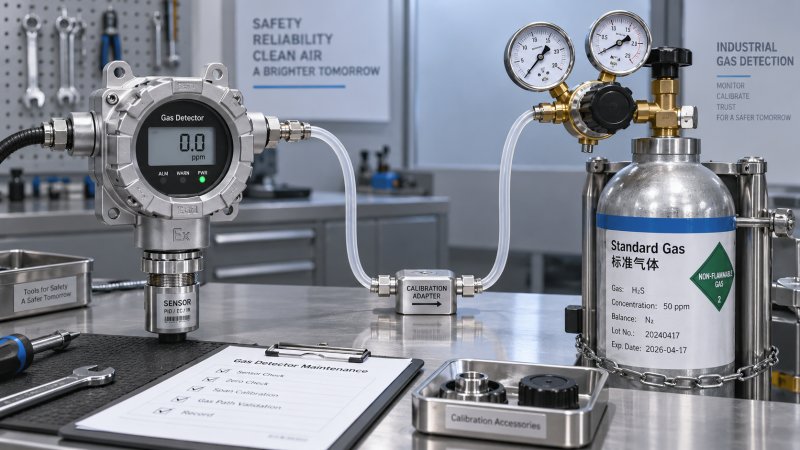
Capture the as-found condition before changing settings
Record the instrument model, serial number, sensor type, target gas, measuring range, firmware where relevant, and installation date. Retrieve previous calibration results, fault logs, and exposure history. Note whether the problem followed a shutdown, washdown, painting job, process upset, power interruption, or sensor replacement.
Trend shape provides clues. A gradual baseline shift suggests a different investigation from sudden spikes during motor starts. Readings that track daily temperature changes deserve an environmental check. Several detectors shifting during one maintenance activity may indicate shared exposure or a common test-gas problem rather than simultaneous sensor aging.
Inspect accessible components without unauthorized disassembly. Look for blocked diffusion openings, damaged splash guards, wet filters, loose connectors, corrosion, and compromised seals. On pumped systems, check tubing, inlet filters, condensate traps, pump status, and flow diagnostics. A leaking sample line may dilute the gas reaching the sensor; a restricted line may delay its arrival. Neither problem is corrected by adjusting span.
Verify the calibration gas and delivery system
A known gas concentration is only useful if it reaches the sensing element as intended. Check the cylinder label and certificate against the detector procedure: gas identity, concentration, balance gas, stated uncertainty, expiry date, and storage requirements. Confirm that the cylinder remains within its supplier's usable-pressure limits.
The balance gas matters. Catalytic combustible sensors require sufficient oxygen for their sensing reaction. Some calibration mixtures suitable for another technology may therefore be inappropriate. Reactive gases can also be lost on unsuitable regulators or tubing surfaces, causing an apparent low response even when the detector is functioning correctly.
- Use the manufacturer-specified calibration adapter, regulator arrangement, and flow rate.
- Check tubing compatibility, leaks, restrictions, and the required purge time.
- Allow the prescribed warm-up and stabilization periods before assessing response.
- Do not pressurize a diffusion sensor or restrict an adapter outlet unless the approved procedure requires it.
- If several instruments fail against one setup, verify that setup with a separate suitable reference before adjusting the fleet.
Do not invent a universal stabilization time or acceptance tolerance. These depend on the sensor, gas, delivery arrangement, and instrument specification. Use the manufacturer's limits and any additional site requirements.
Match the suspected cause to the sensor technology
“Gas sensor drift” describes a symptom, not a single failure mechanism. The sensing principle determines which environmental effects and contaminants deserve attention.
Electrochemical sensors
Electrochemical toxic-gas sensors can respond to gases other than their intended target. Check the manufacturer's cross-sensitivity information against nearby process chemicals, cleaning agents, and maintenance materials. Temperature and humidity changes can affect baseline or response, while prolonged unsuitable conditions may damage the sensor. A temporary recovery after conditions stabilize does not establish long-term fitness.
Look at exposure history alongside age. A sensor within its expected service life may still be compromised by severe exposure. Conversely, age alone does not prove that an otherwise compliant sensor is the source of a wiring or sampling fault.
Catalytic combustible-gas sensors
Catalytic elements may lose sensitivity through poisoning or inhibition. Silicone-containing products and certain sulfur-containing compounds are recognized concerns, although susceptibility varies by design. Oxygen deficiency can also produce an unreliable combustible-gas response.
An apparently normal zero reading does not rule out a poisoned element. Evaluate its response to the approved test gas and review relevant exposures. Do not assume that increasing calibration gain restores the sensor's original detection capability.
Infrared and photoionization detectors
Infrared detectors avoid catalytic poisoning but are not maintenance-free. Contaminated optical surfaces, condensation, obstructed gas access, and pressure or temperature effects can affect performance. Cleaning must follow the approved procedure; inappropriate solvents or abrasion can damage optical components.
Photoionization detectors, where used, need attention to lamp condition, contamination, humidity effects, and response-factor settings. Their readings often represent calibration-gas equivalents rather than a selective measurement of one compound. A changed vapor mixture can change the indicated concentration without an actual calibration drift.
Calibrate, then prove that the correction holds
Once the atmosphere, test setup, and instrument condition are understood, perform the manufacturer-approved calibration sequence. Preserve the as-found zero and span readings before adjustment, then record the as-left results. Where diagnostics expose sensitivity, gain, or remaining-life indicators, retain those values too. Repeatedly increasing gain may conceal deterioration rather than resolve it.
After calibration, verify performance as the procedure requires, including response, recovery, and alarm operation. A bump test demonstrates response and relevant alarm function; it is not equivalent to a full accuracy calibration. For fixed systems, verify signal transmission and required outputs under controlled conditions, with any alarm inhibition managed through the site's authorization process.
A detector that passes immediately but drifts again after returning to service needs further investigation. Check whether installation conditions differ from calibration conditions, whether contamination remains in the sample path, and whether the instrument has fully stabilized. Do not keep recalibrating without investigating the recurrence.
Know when replacement or escalation is justified
Replacement is generally justified when the sensor fails approved acceptance criteria, cannot complete calibration, shows unacceptable response or recovery, reports an end-of-life condition, or repeatedly drifts after external causes have been addressed. Suspected irreversible poisoning and physical damage also warrant manufacturer guidance or replacement. There is no universal drift percentage that applies across industrial gas detectors.
For escalation, send a compact evidence package: as-found and as-left readings, gas certificate details, regulator and flow information, environmental conditions, fault history, exposure notes, and actions taken. This is far more useful than reporting that “the sensor is unstable.” Confirm replacement compatibility, configuration requirements, and post-installation testing before returning the channel to service.
GIH's instrumentation intelligence approach connects maintenance findings with supplier evaluation: assess access to application-specific manuals, cross-sensitivity data, diagnostic support, approved accessories, and replacement availability—not merely the detector's headline specification. Recurring drift can expose a mismatch between the sensing technology and the installation environment that another identical sensor will not solve.
Close the job only after required checks pass, inhibits are removed, protective functions are restored, and the maintenance record is complete. If the cause remains uncertain, keep the affected instrument out of safety-critical service and maintain approved alternative protection until that uncertainty is resolved.
Recommended for You
 How to troubleshoot sensor drift in industrial gas detectorsIndustrial gas detectors showing sensor drift? Learn how to verify calibration gas, identify root causes, and determine when sensor replacement is needed for reliable monitoring.
 How to judge whether a competitive price reflects real valueCompetitive Price: learn how to compare scope, compliance, performance, and lifecycle costs to identify real value, reduce risk, and make smarter purchasing decisions.
 When custom gas analysis is the right fit for complex process streamsCustom gas analysis for complex process streams: learn when tailored sampling, interference control, and reliable measurement design deliver confident decisions.
 When does a laser gas analyzer meet stack emissions monitoring needs?Laser gas analyzer for stack emissions: learn when it delivers fast, reliable data, how to assess installation risks, and what to verify for CEMS compliance.
 How to select a hazardous gas analyzer for confined spacesHazardous gas analyzer selection for confined spaces: compare sensors, sampling, certifications, alarms, and maintenance to protect workers and choose with confidence.
 When is a single gas analyzer sufficient for workplace safety monitoring?Discover when a single gas analyzer delivers reliable workplace safety monitoring, and learn the key limits, calibration needs, and risks that require broader detection.
 How to choose an ambient gas analyzer for low-level leak detectionAmbient gas analyzer selection for low-level leak detection: compare sensitivity, cross-sensitivity, sampling design, alarms, and calibration for reliable site performance.
 How to tell when an oxygen sensor needs replacementOxygen sensor replacement signs explained: learn how live data, fault codes, wiring checks, and exhaust inspections pinpoint the real issue before you buy.
 How laser gas analyzers improve combustion control in steel furnacesLaser gas analyzer for steel industry applications delivers fast in-situ O₂ and CO data to optimize furnace combustion, cut fuel waste, and improve steel heating stability.
 How to verify whether explosion proof equipment meets site requirementsExplosion proof equipment verification made practical: match zones, gas or dust groups, temperature classes, certificates, and installation conditions for confident compliance.
 How industrial gas analysis helps detect contamination before releaseIndustrial Gas Analysis helps detect moisture, oil, oxygen, and toxic contaminants before release—protecting processes, ensuring compliance, and reducing costly risks.
 When is electrochemistry detection the right choice for water analysis?Electrochemistry detection for water analysis: learn when fast, reliable monitoring of ions, chlorine, pH, and more delivers actionable results.
 How industrial standards reduce quality risks in supplier selectionIndustrial Standard guidance helps quality and safety managers reduce supplier risks, verify compliance, strengthen traceability, and build resilient instrumentation supply chains.
 When does a multi-component system reduce installation complexity?Multi component systems reduce installation complexity when they eliminate field interfaces, streamline commissioning, and provide proven compatibility. Learn how to assess total cost and supplier accountability.
 How to size an industrial control shelter for outdoor equipmentIndustrial control shelter sizing guide: optimize layout, HVAC, access, safety, and expansion space for reliable outdoor equipment operations.
 How flue analysis helps verify combustion efficiencyFlue analysis verifies combustion efficiency by assessing O2, CO, CO2, and stack temperature to identify excess air, incomplete combustion, and heat losses.
 How to select industrial gas detectors for confined spacesIndustrial gas detectors for confined spaces: learn how to match sensors, sampling methods, alarms, and certifications to real atmospheric hazards.
 When does a laser oxygen analyzer outperform zirconia sensors?Laser oxygen analyzer vs. zirconia sensors: compare speed, selectivity, maintenance, gas chemistry, and installation needs to choose the right oxygen measurement solution.
 How to select a percent range analyzer for process measurementsPercent range analyzer selection made practical: compare accuracy, sample systems, calibration, gas matrix, integration, and lifecycle cost for reliable process measurements.
 How explosion proof analysis verifies safe equipment for hazardous areasExplosion proof analysis verifies hazardous-area equipment by matching certifications, temperature ratings, installation details, and inspection controls for safer compliance.
 When does fixed gas detection need point sensors instead of open-path monitoring?Fixed gas detection: discover when point sensors outperform open-path monitoring for predictable leaks, enclosed zones, local alarms, and safer design decisions.
 How to choose industrial metrology systems for tight-tolerance partsIndustrial metrology guide for tight-tolerance parts: compare CMMs, optical scanners, gauges, uncertainty, workflow, and traceable inspection strategies.
 How process metrology reduces measurement variation in productionProcess metrology reduces production measurement variation by improving traceability, uncertainty control, calibration, and reliable quality decisions.
 How to select an industrial monitoring analyzer for harsh environmentsIndustrial monitoring analyzer selection for harsh environments: evaluate sampling, durability, hazardous-area compliance, accuracy, maintenance, and data reliability.
 How calibration intervals affect test and measurement equipment accuracyTest and measurement equipment calibration intervals directly affect accuracy, risk, compliance, and uptime. Learn how to set evidence-based schedules that protect critical decisions.
 When does process gas monitoring need continuous measurement?Process gas monitoring needs continuous measurement when rapid changes threaten safety, quality, compliance, or uptime. Learn how to specify reliable, actionable monitoring systems.
 How to prevent false alarms in power plant instrumentationPower plant instrumentation guide: prevent false alarms with reliable signal checks, smarter alarm settings, mode-based control, and actionable operator responses.
 How fixed gas detectors help prevent leaks in enclosed workspacesFixed gas detectors provide continuous leak monitoring in enclosed workspaces, enabling faster alarms, safer responses, and stronger protection for people and processes.
 How industrial gas analysis helps detect process contamination earlyIndustrial Gas Analysis helps detect oxygen, moisture, and hydrocarbon contamination early, enabling faster fault isolation, safer operations, and stronger process control.
 What drives environmental compliance continuous monitoring setup cost?Environmental compliance continuous monitoring setup cost: uncover hidden expenses, compare bids accurately, and build a reliable, audit-ready system.
 How to select gas analysis equipment for continuous emissions monitoringGas analysis equipment selection guide for reliable continuous emissions monitoring—compare technologies, sampling, calibration, compliance, and maintenance needs.
 What detection limit is needed for NH3 environmental monitoring?High accuracy NH3 analyzer for environmental monitoring: learn how to set the right detection limit, improve sampling reliability, and make defensible decisions.






Search Categories
Search Categories
- Smart Meters & Power Quality
- Transformer Gas Analyzers
- BESS Thermal Runaway Detectors
- Energy, Power & Smart Grid Monitoring
- Optical Profilers & CMM
- Ultrasonic & X-Ray NDT
- Calibration Standards
- Precision Metrology & NDT
- Water Quality Analyzers
- CEMS & VOCs Monitors
- Price Trends
- Import & Export Updates
- Market Trends
- Industry News
- Industry Insights
Latest Article
- How to troubleshoot sensor drift in industrial gas detectorsIndustrial gas detectors showing sensor drift? Learn how to verify calibration gas, identify root causes, and determine when sensor replacement is needed for reliable monitoring.Posted by:
- How to judge whether a competitive price reflects real valueCompetitive Price: learn how to compare scope, compliance, performance, and lifecycle costs to identify real value, reduce risk, and make smarter purchasing decisions.Posted by:
- When custom gas analysis is the right fit for complex process streamsCustom gas analysis for complex process streams: learn when tailored sampling, interference control, and reliable measurement design deliver confident decisions.Posted by:
Please give us a message
